
Number Systems and Bitwise Operations — Complete Guide
Learn base conversion, binary masks, two’s complement, integer ranges and register operations, with worked embedded-system examples.
Use the Number Base Converter to reproduce every integer example below. Binary, decimal, hexadecimal and octal describe the same integer with different digit sets. Electronics uses binary for logic states and registers, hexadecimal for compact byte dumps and addresses, decimal for human measurements, and octal for compact three-bit groups or permission masks.
1. Bases and positional notation
Base 2 uses 0–1; base 8 uses 0–7; base 10 uses 0–9; base 16 uses 0–9 and A–F, where A = 10 and F = 15. For digits dᵢ in base b, the value is N = Σ dᵢ × bⁱ, starting at i = 0 on the right. Leading zeros do not change the mathematical value, but can communicate a register width. The following table covers 0 through 15.
| DEC | BIN | HEX | OCT |
|---|---|---|---|
| 0 | 0000 | 0 | 0 |
| 1 | 0001 | 1 | 1 |
| 2 | 0010 | 2 | 2 |
| 3 | 0011 | 3 | 3 |
| 4 | 0100 | 4 | 4 |
| 5 | 0101 | 5 | 5 |
| 6 | 0110 | 6 | 6 |
| 7 | 0111 | 7 | 7 |
| 8 | 1000 | 8 | 10 |
| 9 | 1001 | 9 | 11 |
| 10 | 1010 | A | 12 |
| 11 | 1011 | B | 13 |
| 12 | 1100 | C | 14 |
| 13 | 1101 | D | 15 |
| 14 | 1110 | E | 16 |
| 15 | 1111 | F | 17 |
2. Conversions step by step
Binary → decimal. Expand powers of two: 10101010₂ = 1×128 + 0×64 + 1×32 + 0×16 + 1×8 + 0×4 + 1×2 + 0×1 = 170₁₀.
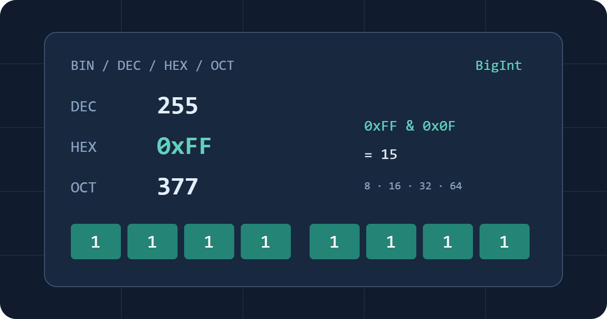
Decimal → binary. Repeatedly divide by 2 and record remainders. For 13: 13 = 2×6+1; 6 = 2×3+0; 3 = 2×1+1; 1 = 2×0+1. Read remainders from bottom to top: 1101₂. For 255 the result is 11111111₂ = FF₁₆ = 377₈.
Binary → hexadecimal. Group from the right in fours, padding only the leftmost group: 1010 1011 1100 1101₂ = A B C D₁₆. Four bits represent exactly one hex digit because 16 = 2⁴.
Hexadecimal → binary. Replace each hex digit by four bits: 0x2F → 0010 1111₂ → 47₁₀. Accepting A–F in either case changes no value.
Octal. Group binary digits from the right in threes because 8 = 2³: 11111111₂ → 011 111 111₂ = 377₈. Conversely, 17₈ → 001 111₂ = 15₁₀. Decimal conversion uses 377₈ = 3×8² + 7×8 + 7 = 255; converting decimal to octal uses repeated division by 8.
3. Arithmetic and exact integers
Addition, subtraction and multiplication work independently of notation: 0x0F + 0b1 = 16, 20 − 7 = 13, 0o7 × 0x3 = 21. Binary addition carries when a column reaches two: 0111 + 0001 = 1000.
This tool uses BigInt throughout integer conversion and calculation, including values beyond 2⁵³ − 1. Integer division truncates toward zero: −7 ÷ 3 = −2. The % operation is a remainder, not a nonnegative Euclidean modulo: −7 % 3 = −1. Always a = (a / b) × b + (a % b) for nonzero b. Division and remainder by zero are errors.
4. AND, OR, XOR and NOT
Each column is processed independently. AND keeps positions set in both inputs; OR sets positions set in either; XOR sets positions that differ; NOT flips every bit within the chosen width.
| A | B | A AND B | A OR B | A XOR B | NOT A |
|---|---|---|---|---|---|
| 0 | 0 | 0 | 0 | 0 | 1 |
| 0 | 1 | 0 | 1 | 1 | 1 |
| 1 | 0 | 0 | 1 | 1 | 0 |
| 1 | 1 | 1 | 1 | 0 | 0 |
For eight-bit patterns: 11111111 & 00001111 = 00001111 (15); 10100000 | 00001111 = 10101111 (175); 10101010 ^ 11111111 = 01010101 (85). NOT on unsigned eight-bit 00001111 gives 11110000 (240). In Auto, there is no finite mask: ~15 = −16, following the BigInt identity ~x = −x − 1.
5. Signed values and two’s complement
An unsigned w-bit pattern has value Σ bᵢ2ⁱ. Its range is 0 … 2ʷ−1. For signed two’s complement, the most significant bit has weight −2ʷ⁻¹, and the range is −2ʷ⁻¹ … 2ʷ⁻¹−1. If the high bit is set, subtract 2ʷ from the unsigned interpretation.
On eight bits, FF = 255 − 256 = −1 and 80 = 128 − 256 = −128. To encode −5, take 00000101, invert to 11111010, then add 1 to obtain 11111011 (FB). On sixteen bits, FFFF is −1. Two’s complement is a width-dependent binary representation, not a different base.
| Bits | Unsigned | Signed |
|---|---|---|
| 8 | 0 … 255 | −128 … 127 |
| 16 | 0 … 65535 | −32768 … 32767 |
| 32 | 0 … 4294967295 | −2147483648 … 2147483647 |
| 64 | 0 … 18446744073709551615 | −9223372036854775808 … 9223372036854775807 |
The converter treats DEC as a mathematical value. At a fixed width, nonnegative BIN/HEX/OCT inputs are raw patterns, so signed eight-bit HEX FF is valid and gives DEC −1; DEC 255 is rejected. Negative literals are mathematical values and must fit the selected range. No input is silently truncated. Non-decimal outputs are padded to the selected bit width, with up to two unused high bits in the final octal digit.
Auto imposes no width, and even the unsigned selector does not restrict mathematical negative values. Negative Auto output uses a minus sign and magnitude, not a finite two’s-complement word. Its visual view shows at most the lowest 128 magnitude bits; all conversions and copies retain the full integer.
6. Shifts and overflow
A left shift by k multiplies an unbounded integer by 2ᵏ: 0x01 << 4 = 0x10 = 16. At a fixed width the bitwise result is masked with 2ʷ−1. Thus unsigned eight-bit 0x80 << 1 has exact result 256 but stored result 0, accompanied by an overflow warning. Signed eight-bit 0x40 << 1 becomes −128 and also warns because the exact result 128 is outside the signed range.
Logical right shift inserts zeros: unsigned eight-bit FF >> 1 = 7F = 127. Arithmetic right shift repeats the sign: signed eight-bit FF >> 1 = FF = −1, and 80 >> 1 = C0 = −64. Negative arithmetic shifts round down: −3 >> 1 = −2, unlike integer division −3 / 2 = −1.
B is always a decimal nonnegative shift count, independent of its former base selector or word size. The tool permits 0–65536 to bound work per calculation; counts are not reduced modulo 32 or the word width. Shifting an eight-bit unsigned value right by 8 gives 0. Arithmetic overflow, such as unsigned eight-bit 255 + 1 or signed −128 / −1, is rejected and the exact DEC result is reported. Auto bitwise operations use BigInt’s unbounded signed semantics.
7. Registers, masks and flags
For an STM32F407, the GPIO input register exposes pin states. After configuring the peripheral and its clock, a CMSIS device header permits this illustrative access:
uint32_t snapshot = GPIOA->IDR;
uint32_t pin5 = (snapshot >> 5u) & 1u;
uint32_t field = (snapshot >> 4u) & 0x0Fu;
GPIOA->BSRR = 1u << 5u;
If the snapshot is 0xB0, pin5 is 1 and bits 7:4 form 0xB = 11. The BSRR write sets output bit 5 without a software read-modify-write of ODR; pin mode still determines external behaviour. Consult the exact device manual for clocks, reserved bits and write-one-to-clear fields before adapting any register operation. A snapshot avoids multiple peripheral reads with potentially different values.
These flag operations apply to a local unsigned variable:
uint32_t flags = 0u;
uint32_t mask = 1u << 3u;
flags |= mask;
flags &= ~mask;
flags ^= mask;
uint32_t active = (flags & mask) != 0u;
The mask 0x08 selects bit 3. OR sets it, AND with its complement clears it, XOR toggles it, and the final expression tests it. Read-modify-write is not automatically atomic for shared memory or hardware registers; use the documented register mechanism or appropriate synchronization.
8. CAN, UART, SPI, ADC and FPGA applications
For bytes 0x12 and 0x34, a protocol-defined big-endian 16-bit field is (0x12 << 8) | 0x34 = 0x1234 = 4660; little-endian interpretation gives 0x3412 = 13330. CAN payload layouts come from the message specification or DBC. UART byte framing and SPI bit order do not by themselves define the byte order of a multibyte application value. See the UART guide and SPI guide.
For an unsigned 12-bit ADC, 0xABC = 2748 is valid in the range 0–4095. A simple endpoint display mapping with Vref = 3.3 V gives 2748 × 3.3 / 4095 ≈ 2.2145 V. This is an approximate display convention; ideal quantization step size is 3.3/4096 V, and the real transfer depends on the ADC specification. Signed ADC data may instead use two’s complement or offset binary. Check alignment and coding, then use the ADC/DAC calculator.
In FPGA and microcontroller code, declare width and signedness explicitly. SystemVerilog 8'hFF is an eight-bit unsigned pattern; 8'shFF denotes signed −1. Unsized literals, expression sizing and signed promotion can change a result. This calculator’s defined masking behaviour does not reproduce every C/C++ or HDL promotion rule.
9. Frequently asked questions
How do I convert binary to hexadecimal?
Group bits from the right in fours and map each group to 0–F. For example, 1111 0000 becomes F0. Pad the leftmost group with zeros if necessary.
What is the difference between signed and unsigned integers?
Unsigned uses all bits for a nonnegative value. Two’s-complement signed interpretation gives the most significant bit negative weight. The same FF pattern is 255 unsigned or −1 signed on eight bits.
How does two’s complement work?
For a negative value on w bits, encode 2ʷ plus that value. Equivalently, invert the positive magnitude and add one within the selected width.
What is a bitwise XOR operation?
XOR produces one where its input bits differ. XOR with a mask toggles exactly the selected positions, so AA XOR FF gives 55.
How do I extract bits from a register?
Shift the desired field down, then AND with a mask of its width. To extract bits 7:4, use (reg >> 4) & 0x0F. Read volatile registers according to their hardware semantics.
Why does FF sometimes mean −1?
Signed interpretation depends on width. FF has its sign bit set on eight bits and means −1; 00FF on sixteen bits is +255.