
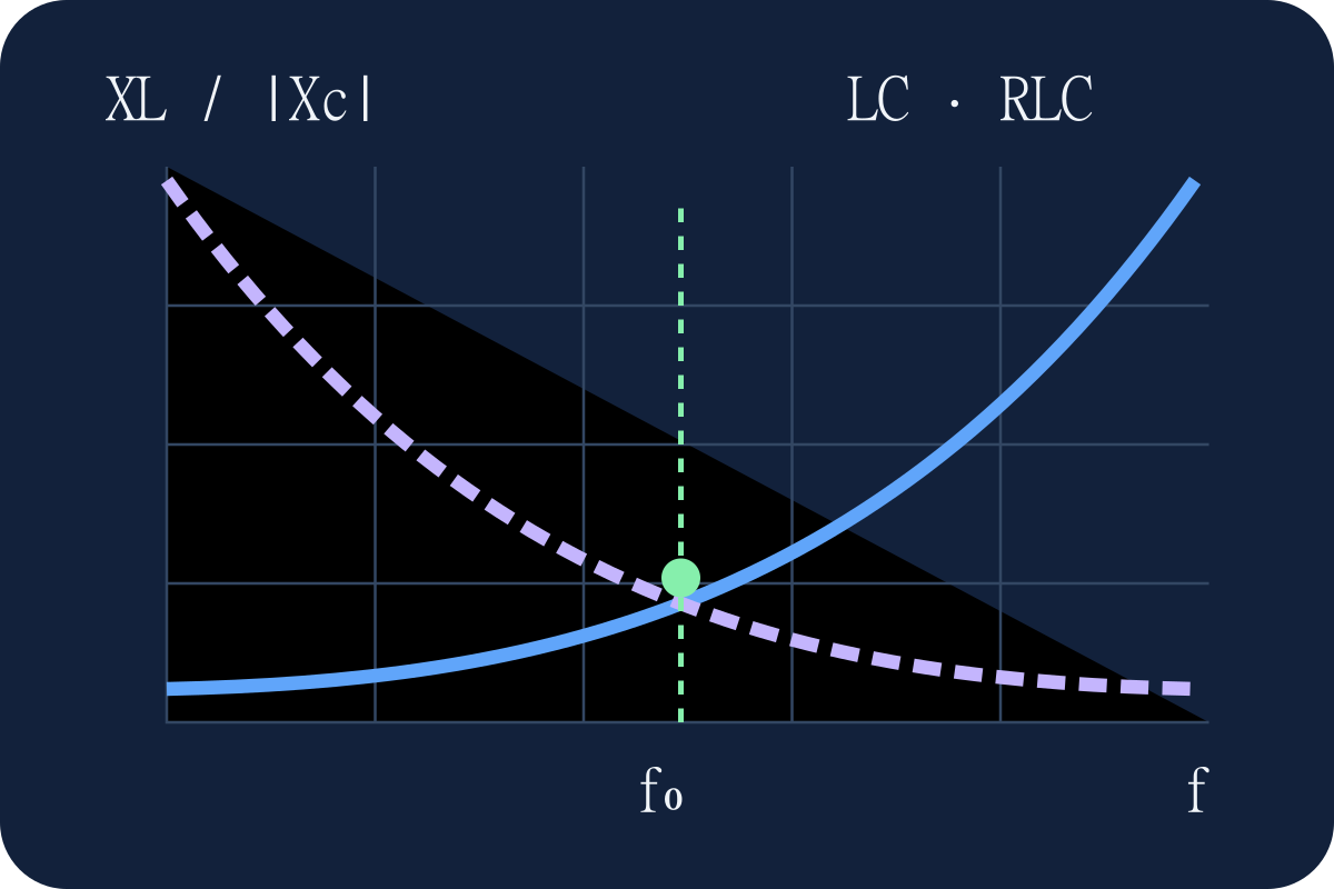
Understanding Reactance and LC/RLC Resonance
Understand capacitive and inductive reactance, LC resonance, RLC impedance, quality factor and bandwidth with formulas and worked examples.
Use the Reactance / Resonance Calculator to explore a component at one frequency, find an ideal LC resonance, or analyse a complete series RLC circuit. This guide develops the equations behind those results and explains how to interpret them before selecting real parts. All formulas use hertz, henries, farads and ohms unless a conversion is shown explicitly.
1. What electrical reactance means
Reactance describes the opposition associated with reversible energy storage in an alternating-current circuit. An inductor stores magnetic energy; a capacitor stores electric energy. During a sinusoidal cycle, an ideal reactive element returns the energy it received. This changes the timing of voltage relative to current without dissipating average power inside the ideal element.
Reactance depends on frequency. A capacitor that strongly restricts a low-frequency current may readily pass a much higher-frequency signal. An inductor usually behaves in the opposite way below its self-resonant region. A single component value therefore does not describe its AC behaviour without an operating frequency and a circuit context.
2. Resistance, reactance and impedance
Resistance R is the real part of impedance and represents dissipation in the simple passive model. Reactance X is its imaginary part. With the exp(jωt) phasor convention, complex impedance is Z = R + jX, where j² = −1 and ω = 2πf. Both R and X use ohms, but they describe different physical effects.
The magnitude is |Z| = √(R² + X²), rather than R + |X|. Its angle is φ = atan2(X, R). A positive impedance angle means source voltage leads current; a negative angle means current leads source voltage. Keep this distinction when comparing a calculator phase with an oscilloscope measurement of current relative to voltage.
3. Inductive reactance
The time-domain relation v = L di/dt gives ZL = jωL under sinusoidal steady-state conditions. Thus the signed inductive reactance is XL = 2πfL. Doubling either frequency or inductance doubles XL. For an ideal inductor, voltage leads current by 90°.
This does not make an inductor a frequency-dependent resistor. Its ideal average loss remains zero. Winding resistance, core loss and skin effect introduce real power dissipation in actual inductors, and those contributions are excluded from XL. When estimating total loss, consult impedance or Q curves at the intended frequency and current.
4. Capacitive reactance
Starting from i = C dv/dt gives ZC = 1/(jωC) = −j/(ωC). The signed capacitive reactance is negative, while the commonly quoted magnitude is |Xc| = 1/(2πfC). Increasing frequency or capacitance reduces that magnitude. Ideal capacitor current leads voltage by 90°.
The negative sign is a complex-impedance convention, not negative dissipation or negative capacitance. On a magnitude chart both XL and |Xc| are positive. At zero frequency the ideal capacitor is an open circuit in steady DC conditions; the division formula must not be evaluated with f = 0. The calculator requests strictly positive f and C instead.
5. Understanding ideal LC resonance
An LC pair exchanges energy between WL = Li²/2 and WC = Cv²/2. Its natural angular frequency is ω₀ = 1/√(LC) and its resonance frequency is f₀ = 1/(2π√(LC)). At f₀, the reactance magnitudes are equal to √(L/C).
For a series connection their imaginary impedances cancel. An ideal parallel LC combination instead has cancelling susceptances and an unbounded impedance at resonance. The same ideal LC frequency does not imply the same terminal behaviour. This calculator’s RLC impedance mode always assumes a series connection.
6. Series RLC impedance, phase and resonance
For series elements, add their complex impedances: Z = R + j(ωL − 1/(ωC)). Define X = XL − |Xc|. Below f₀ the result is capacitive; above f₀ it is inductive. At f₀ the reactances cancel, |Z| reaches R, and φ is zero when R is positive.
Under a fixed sinusoidal source voltage, current magnitude is |I| = |V|/|Z|. The impedance minimum therefore corresponds to a current maximum. For R = 0 exactly at f₀, Z = 0 and its angle is undefined. A lossless circuit driven at resonance does not have a bounded forced sinusoidal steady state; the zero-impedance result is an ideal limit, not a prediction of finite component currents.
7. Quality factor and exact bandwidth
For positive series resistance, Q = ω₀L/R = √(L/C)/R and BW = f₀/Q = R/(2πL). Q is dimensionless and BW is in hertz. Higher Q narrows the current response and can produce substantial voltage magnification across L and C. These relations describe this series topology and its specified total series resistance.
At half the maximum resistor power, current is 1/√2 of its resonant value, so |Z| = √2 R and |X| = R. This is a −3.0103 dB current-amplitude point, conventionally called −3 dB. The impedance magnitude has risen, rather than fallen, by that amount.
Solving the two reactance equations gives α = R/(2L), ω₁ = √(ω₀² + α²) − α, ω₂ = √(ω₀² + α²) + α, and f₁,₂ = ω₁,₂/(2π). Exactly, f₂ − f₁ = BW and √(f₁f₂) = f₀. Their arithmetic midpoint generally exceeds f₀; f₀ ± BW/2 is only a high-Q approximation. The calculator uses a rationalized lower root to avoid subtracting nearly equal numbers.
As R approaches zero, Q tends to infinity and BW tends to zero. At R = 0 there is no resistor power defining a pair of half-power crossings, so those frequencies are deliberately left undefined.
8. Practical electronic applications
Reactance estimates help compare coupling capacitors, identify loading by an input network, and investigate ringing. For a coupling capacitor, compare |Xc| with the complete source and load impedance. For an inductor used as a choke, check whether XL is sufficiently large across the relevant band while respecting current and saturation limits.
Use the RC / RL Filter calculator for first-order cutoff and loading, Capacitor Charge for charging transients, and Series / Parallel Capacitors to determine equivalent capacitance before applying the LC formulas. A transient charging time and an AC reactance answer different questions even when they involve the same capacitor.
9. Three worked calculations
A 100 nF capacitor at 1 kHz
Given C = 100 nF = 100 × 10⁻⁹ F and f = 1 kHz = 1,000 Hz, use |Xc| = 1/(2πfC). Substitution gives 1/(2π × 1,000 × 100 × 10⁻⁹) = 1,591.5494 Ω, or approximately 1.59155 kΩ. Its signed reactance is −1.59155 kΩ. A 1 V RMS voltage across this capacitor would produce approximately 0.628 mA RMS in the ideal model.
A 10 mH inductor at 1 kHz
Given L = 10 mH = 0.010 H and f = 1,000 Hz, use XL = 2πfL. Substitution gives 2π × 1,000 × 0.010 = 62.83185 Ω, approximately 62.83 Ω. Its signed reactance is positive. These first two examples use different components and do not form the LC pair in the next example.
An LC circuit with 10 µH and 100 nF
Given L = 10 × 10⁻⁶ H and C = 100 × 10⁻⁹ F, LC = 10⁻¹² s². Substitution in f₀ = 1/(2π√LC) gives 1/(2π × 10⁻⁶) = 159,154.943 Hz, approximately 159.155 kHz. Also ω₀ = 1,000,000 rad/s, T₀ = 6.28319 µs, and XL = |Xc| = 10 Ω.
Adding R = 1 Ω in series gives Q = 10, BW ≈ 15.9155 kHz and |Z(f₀)| = 1 Ω. The exact half-power frequencies are about 151.396 and 167.312 kHz. Their difference is the bandwidth, and their geometric mean is the resonance frequency.
10. Limits of ideal models
Component tolerances shift resonance. For small changes, Δf₀/f₀ ≈ −½(ΔL/L + ΔC/C); independent random tolerances require a statistical treatment instead of simply assuming worst-case signs. Capacitor bias and temperature dependence can change C substantially, while inductor saturation makes L dependent on current.
ESR, winding resistance, core losses, source impedance and load impedance affect damping. Parasitic inductance gives capacitors a self-resonance, and winding capacitance does the same for inductors. Beyond that region a nominal capacitor can appear inductive. PCB interconnects may also require a distributed transmission-line model. Verify the calculation using manufacturer data, suitable simulation and measurement.
11. Technical FAQ
Does resonance mean the circuit has no impedance?
Only an ideal lossless series LC has zero terminal impedance at f₀. A series RLC retains R. A parallel topology has a different response. Cancellation of reactances does not eliminate stored energy or internal element voltages.
Is f₀ the damped ringing frequency?
Not generally. For an underdamped free series response, ωd = √(ω₀² − α²); if α ≥ ω₀ there is no oscillatory free response. The forced-series-current maximum remains at ω₀ in this ideal constant-R model.
Why do the charts use a logarithmic frequency axis?
Equal horizontal distances represent equal frequency ratios, allowing several decades to be inspected. The vertical axis remains a linear magnitude in ohms. Use the pointer, touch or keyboard slider to read values; closely spaced features may need numerical results for precise interpretation.
12. Sources and references
- OpenStax, University Physics Volume 2, section 15.3: phasor treatment of a series RLC circuit.
- MIT 6.101, Spring 2020, Lecture 1, slide 61: series RLC bandwidth and Q relations.
- Analog Devices, StudentZone, decoupling, part 3: capacitor ESR, ESL and self-resonance.
Return to the calculator to compare the numerical examples with your own values.