
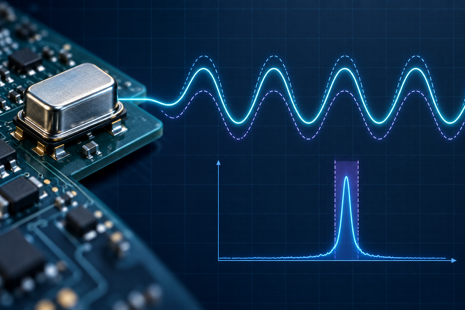
Frequency tolerance: converting PPM, Hz, and period
Convert ppm accuracy into a hertz offset, derive minimum and maximum limits, and connect frequency tolerance to period variation.
Written and technically reviewed byElectroDesignForge Engineering Team
View the editorial process⏱️ Engineering reference
Frequency-control components usually express accuracy or stability as a relative value in parts per million (ppm). The corresponding error in hertz depends on the nominal frequency: the same ±20 ppm means ±0.65536 Hz at 32.768 kHz, but ±2 kHz at 100 MHz.
The PPM to Hz calculator performs both directions of the conversion and evaluates the exact period span.
Quick Reference
For a nominal frequency f and a symmetric tolerance ±p ppm:
relative variation = p × 10⁻⁶
Δf = f × p × 10⁻⁶
fmin = f − Δf
fmax = f + Δf
period span = Tmax − Tmin = 1/fmin − 1/fmax
For a measured minimum or maximum frequency flimit:
Δf = |flimit − f|
ppm = (Δf / f) × 10⁶
ppb = (Δf / f) × 10⁹ = 1000 × ppm
The calculator treats the entered ppm value as the positive magnitude of a symmetric ± tolerance. In reverse mode, the entered limit defines one side of the same symmetric window.
What PPM Means
PPM is a dimensionless ratio. In frequency work:
1 ppm = 1 × 10⁻⁶ = 0.0001 %
Therefore, ppm is not a fixed number of hertz. Multiplying the relative ratio by the nominal frequency turns it into an absolute frequency offset.
| Nominal frequency | ±1 ppm | ±10 ppm | ±100 ppm |
|---|---|---|---|
| 32.768 kHz | ±0.032768 Hz | ±0.32768 Hz | ±3.2768 Hz |
| 10 MHz | ±10 Hz | ±100 Hz | ±1 kHz |
| 100 MHz | ±100 Hz | ±1 kHz | ±10 kHz |
| 2.4 GHz | ±2.4 kHz | ±24 kHz | ±240 kHz |
The BIPM describes ppm as a relative value of 10⁻⁶. The calculator also reports ppb using the engineering convention 1 ppb = 10⁻⁹, hence 1 ppm = 1000 ppb. Because “billion” has historically been language-dependent, the BIPM and NIST recommend writing the explicit power-of-ten ratio in formal SI work.
Converting PPM to Hertz
Consider a 100 MHz oscillator specified at ±100 ppm:
Δf = 100,000,000 × 100 × 10⁻⁶ = 10,000 Hz
fmin = 99,990,000 Hz
fmax = 100,010,000 Hz
The full frequency window is twice the one-sided variation:
fmax − fmin = 2 × Δf = 20,000 Hz
Keep ±Δf and the full peak-to-peak window distinct. A data sheet marked “±20 ppm” permits 20 ppm below and 20 ppm above nominal, for a total min-to-max span of 40 ppm.
Converting a Frequency Limit to PPM
Suppose a nominal 25 MHz clock is measured at 24.99875 MHz:
Δf = |24,998,750 − 25,000,000| = 1,250 Hz
ppm = (1,250 / 25,000,000) × 10⁶ = 50 ppm
ppb = 50,000 ppb
The sign of flimit − f indicates whether that observation is below or above nominal. A tolerance specification normally reports the magnitude as ±50 ppm. The calculator uses that magnitude to reconstruct the opposite symmetric limit for the chart and period calculation.
If a component has asymmetric limits, calculate each side separately and preserve the signed lower and upper deviations instead of replacing them with a symmetric ± value.
Frequency Error and Period Error
Frequency and period are reciprocal:
T = 1 / f
The lowest frequency produces the longest period, so the exact min-to-max period difference is:
ΔTspan = 1/(f − Δf) − 1/(f + Δf)
       = 2Δf / (f² − Δf²)
For small tolerances, a useful approximation is:
ΔTspan ≈ 2Δf / f² = 2 × ppm × 10⁻⁶ / f
At 100 MHz and ±100 ppm, the exact period span is approximately 2.00000002 ps. The nominal period is 10 ns; the periods at the two frequency limits differ by only about two picoseconds.
At 32.768 kHz and ±20 ppm:
| Quantity | Value |
|---|---|
| One-sided variation, Δf | 0.65536 Hz |
| Minimum frequency | 32,767.34464 Hz |
| Maximum frequency | 32,768.65536 Hz |
| Period span | ≈ 1.2207 ns |
The exact reciprocal calculation matters when the tolerance is wide. It also avoids incorrectly assuming that equal positive and negative frequency offsets produce equal period offsets.
Reading an Oscillator or Crystal Specification
“Frequency tolerance” is often only the initial error near a reference temperature. A complete clock budget may include:
- Initial tolerance: production spread around nominal, commonly specified at 25 °C.
- Temperature stability: additional deviation over the operating-temperature range.
- Aging: long-term change after manufacture and operation.
- Supply and load variation: sensitivity to supply voltage, output load, or crystal load capacitance.
- Pulling and trim error: shift caused by the oscillator circuit, tuning range, or calibration resolution.
- Measurement uncertainty: uncertainty of the counter, reference clock, fixture, and gate time.
Microchip’s crystal-selection guidance separates initial tolerance, temperature stability, and aging. For a guaranteed worst-case budget, add only the limits whose data-sheet definitions and reference conditions are compatible. Root-sum-square treatment is not a substitute for guaranteed worst-case limits unless the error sources are demonstrably independent and statistical.
PPM accuracy is also different from jitter and phase noise. PPM describes a frequency offset or slow stability envelope; jitter describes short-term timing variation. A clock can have excellent ppm accuracy and poor jitter, or the reverse.
Common Mistakes
- Using ppm as though it were hertz. Always multiply by the nominal frequency.
- Confusing ±Δf with the full window. The full frequency span is 2Δf for a symmetric tolerance.
- Subtracting periods in the wrong order. Maximum period occurs at minimum frequency.
- Rounding the input too early. Keep guard digits through the reciprocal calculation, especially at high frequency.
- Adding every ppm number blindly. Confirm reference temperature, operating range, aging interval, and whether a figure is typical or guaranteed.
- Treating a measured endpoint as a complete specification. One observation does not establish temperature, aging, or production limits.