
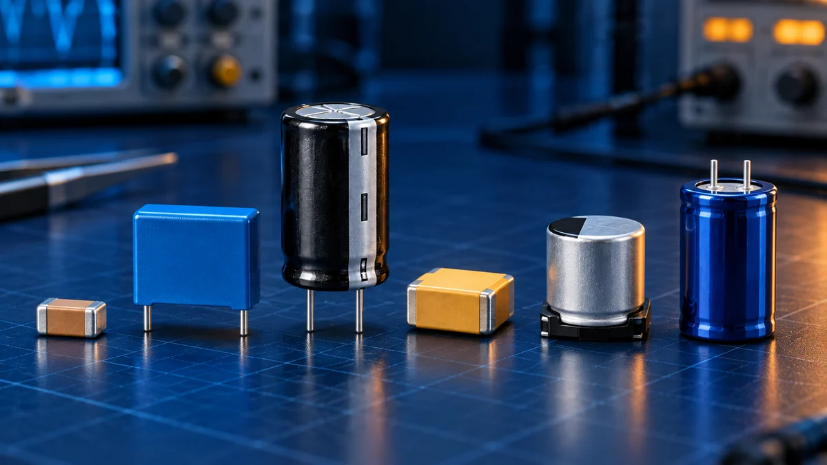
Capacitor technologies comparison
A practical comparison of ceramic, film, aluminium electrolytic, polymer, tantalum, and supercapacitor technologies for selecting the right part.
Written and technically reviewed byElectroDesignForge Engineering Team
View the editorial process📖 Definition
A capacitor technology is defined by its dielectric, electrode system, electrolyte where present, and construction. These choices determine far more than nominal capacitance: polarity, effective capacitance, losses, frequency response, leakage, ripple-current capability, lifetime, and failure behaviour all change with the technology.
The Short Answer
There is no universally “best” capacitor. Select the technology from the circuit’s dominant constraint, then select an exact series and part number from its datasheet.
| Primary need | Technology to evaluate first | Why |
|---|---|---|
| Precision, timing, RF, low loss | C0G / NP0 ceramic or silicon | Very stable capacitance and excellent high-frequency behaviour |
| Local IC decoupling in minimum area | Class 2 MLCC, such as X7R or X5R | Low ESL and high capacitance density |
| Pulse, snubber, resonant or DC-link service | Polypropylene film | Low loss, high pulse capability and non-polar construction |
| Economical bulk smoothing | Aluminium electrolytic | High capacitance and useful voltage range at moderate cost |
| Compact, low-ESR power-rail filtering | Conductive polymer | Low ESR and strong ripple performance |
| Compact solid bulk capacitance | Tantalum | Stable capacitance and high volumetric efficiency when correctly derated |
| Backup energy for seconds or minutes | EDLC supercapacitor | Capacitance in the farad range and high cycle capability |
Most power supplies use more than one technology. A bulk electrolytic or polymer capacitor handles low-frequency energy, while nearby MLCCs close the high-frequency current loop.
Comparison Matrix
The ratings below are qualitative. Package size, voltage rating, dielectric formulation and series can change the result substantially.
| Technology | Polarity | Main strength | Principal limitation | Typical roles |
|---|---|---|---|---|
| C0G / NP0 ceramic | No | Stability, low loss, high self-resonant frequency | Limited capacitance at a given size | RF matching, resonators, precision filters, timing |
| X7R / X5R MLCC | No | Small size, low ESL, high capacitance density | Capacitance falls with DC bias; ageing and mechanical cracking must be considered | Decoupling, bypassing, compact filters |
| Film | No | Low dissipation, pulse current, voltage stability; metallized types can self-heal | Larger volume and usually lower capacitance density | DC links, snubbers, resonant converters, approved mains suppression |
| Wet aluminium electrolytic | Yes, except special bipolar series | High capacitance, broad voltage range, economical bulk storage | Finite electrolyte-dependent life, leakage and higher ESR/ESL | Rectifier smoothing, hold-up, low-frequency bulk filtering |
| Conductive polymer aluminium or tantalum | Yes | Very low ESR, good high-frequency ripple performance, stable low-temperature ESR | Leakage, polarity, voltage range and surge limits remain series-dependent | Regulator input/output filtering, CPU and FPGA rails |
| Solid tantalum with MnO₂ cathode | Yes | Compact, stable solid construction and predictable long-term behaviour when properly applied | Surge sensitivity and potentially energetic short-circuit failure require strict derating | Space-constrained, steady low-voltage rails |
| EDLC supercapacitor | Yes | Extremely high capacitance and repeated charge/discharge capability | Low cell voltage, self-discharge, leakage and balancing for series stacks | Ride-through, memory backup, peak-power support |
“Low ESR” alone is not a complete selection rule. A regulator may require an ESR window for stability, and the interconnect inductance can dominate at high frequency even when the capacitor itself is excellent.
Ceramic Capacitors: C0G / NP0 and Class 2 MLCCs
Ceramic capacitors are compact, non-polar and well suited to surface mounting. Their short current path generally gives them low equivalent series inductance (ESL), which is why MLCCs dominate local high-frequency decoupling.
The dielectric class changes the behaviour:
- C0G / NP0 (Class 1): low loss, negligible ageing, and very small variation with voltage and temperature. Use it for RF, resonant, timing and precision analogue circuits. Available capacitance is lower than with Class 2 dielectrics at the same size.
- X7R, X5R and related Class 2 dielectrics: much higher capacitance density, but capacitance varies with DC bias, temperature, ageing and measurement conditions. The nominal value is not the value guaranteed in the powered circuit.
MLCCs can crack under PCB flex or thermal-mechanical stress, sometimes creating a short circuit. Soft-termination parts, suitable land patterns, orientation and board support can reduce this risk.
For Class 2 parts, read the exact manufacturer curve and calculate the effective capacitance under voltage and temperature.
Film Capacitors
Film capacitors use a plastic film dielectric, commonly polypropylene or polyester. They are non-polar, usually exhibit low dielectric loss, and retain capacitance well with applied DC voltage. Polypropylene is widely used where pulse current, low loss and stability matter.
Metallized film construction can be self-healing: a small dielectric breakdown vaporizes a tiny area of electrode around the fault and isolates it, at the cost of a very small loss of capacitance. Film/foil constructions trade this behaviour for especially high pulse-current capability.
Evaluate film technology first for snubbers, resonant converters, DC links, motor applications and AC filtering. Its principal cost is physical volume. For direct connection to the mains, use only a capacitor with the required X or Y safety approval; a suitable voltage rating by itself is not sufficient.
Aluminium Electrolytic Capacitors
Wet aluminium electrolytics provide large capacitance economically and extend to high voltage ratings. They are a natural choice for rectifier smoothing, hold-up energy and bulk filtering.
Their liquid electrolyte introduces a wear-out mechanism. Core temperature, ripple-current heating, applied voltage and cooling all affect useful life. ESR also varies with frequency and temperature, particularly at low temperature. Treat the datasheet’s rated ripple current, useful life and test conditions as linked specifications.
Standard aluminium electrolytics are polarized. Prevent reverse voltage, respect surge limits and provide voltage balancing when series operation is explicitly supported. Check leakage current when the source is weak or the stored charge must remain for a long time.
Conductive Polymer Capacitors
Conductive polymer replaces a conventional wet electrolyte or manganese-dioxide cathode with a highly conductive material. Polymer aluminium and polymer tantalum parts can therefore achieve very low ESR and low impedance around their resonance, reducing ripple on compact power rails.
They are useful on switching-regulator inputs and outputs and on high-current digital rails. They remain polarized, and low ESR does not remove the need to verify control-loop stability. Voltage rating, surge capability, DC leakage, humidity resistance and reflow sensitivity differ by construction and series.
Hybrid aluminium capacitors combine a conductive polymer with a liquid electrolyte. They aim to balance low ESR, higher working voltage and robustness, but should be treated as a distinct technology when comparing datasheets.
Tantalum Capacitors
Solid tantalum capacitors use a porous tantalum anode and tantalum pentoxide dielectric, giving high capacitance per volume and stable capacitance with bias compared with Class 2 MLCCs. Traditional parts use a manganese-dioxide cathode; polymer tantalum is covered in the polymer family above.
Tantalum capacitors are polarized and sensitive to excessive voltage, reverse voltage and high-energy surge conditions. A damaged MnO₂ tantalum part can fail short and the failure can be energetic. Follow the manufacturer’s application-specific voltage-derating and surge-current guidance rather than applying one universal percentage.
Use them where compact solid bulk capacitance and long-term stability justify the cost and where the power source, series impedance and protection make the failure mode acceptable.
EDLC Supercapacitors
Electric double-layer capacitors bridge the gap between conventional capacitors and batteries. Their farad-level capacitance suits ride-through, memory backup, energy harvesting and short peak-power events.
The stored energy is:
E = ½ × C × V²
The output voltage falls continuously as energy is removed, so usable energy depends on both the initial and minimum circuit voltage. Individual cells have low working voltage. Series stacks need voltage management because capacitance and leakage tolerances can unbalance the cell voltages.
Supercapacitors also have meaningful self-discharge, leakage and ESR. They are not substitutes for MLCCs or electrolytics in high-frequency ripple filtering, and temperature plus operating voltage strongly influence life.
Frequency, ESR and ESL
An ideal capacitor has reactance that falls as frequency rises. A real capacitor also contains ESR and ESL:
Z(f) ≈ ESR + j × (2πf × ESL − 1 / (2πf × C))
Below self-resonance, the part behaves mainly as a capacitor. At self-resonance, impedance reaches a minimum largely set by ESR. Above it, ESL makes the component behave increasingly like an inductor.
This explains why one very large capacitor does not replace a small capacitor placed close to an IC. Compare manufacturer impedance curves at the operating bias and temperature, then include pad, via and plane inductance in the layout decision.
Selection Checklist
- Define the required capacitance or stored energy at the actual operating voltage.
- Identify the important frequency range and whether the load needs charge storage, low impedance, precision or pulse handling.
- Check polarity, reverse voltage, steady voltage, transients and the manufacturer’s derating guidance.
- Calculate effective capacitance with tolerance, DC bias, temperature and ageing where applicable.
- Verify ESR, ESL, self-resonant frequency, ripple current and predicted self-heating.
- Check leakage, self-discharge and standby-current limits.
- Check useful life, humidity, mechanical stress, mounting and the relevant failure mode.
- Require the correct safety approval for mains-connected or safety-critical positions.
- Validate the exact part with manufacturer curves, a circuit model and measurements when performance is critical.
Related Tools and References
- Capacitor derating curves — estimate capacitance retention with voltage and temperature.
- Capacitor marking-code decoder — interpret common capacitance, tolerance, voltage and dielectric markings.
- Series and parallel capacitor calculator — calculate equivalent capacitance, voltage sharing and stored energy.
- Capacitor charge calculator — analyse RC charging, energy and inrush current.
- RC / RL filter calculator — evaluate how a real capacitance value moves a filter corner.
Bibliography
- TDK — Capacitors selection guide
- TDK — MLCC characteristics for resonant circuits
- TDK Electronics — General technical information for aluminium electrolytic capacitors
- KEMET — Pulse, snubber and PFC film capacitors
- Panasonic — Understanding polymer and hybrid capacitors
- KYOCERA AVX — Conductive polymer capacitor guidelines
- Eaton — Supercapacitor application guidelines