
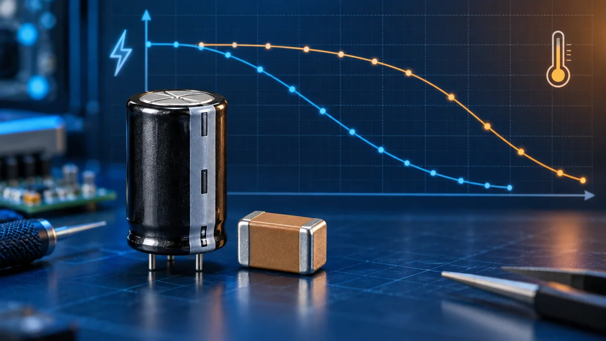
Capacitor voltage and temperature derating
Rated voltage, DC bias, temperature codes, effective capacitance, and a method for reading manufacturer curves.
Written and technically reviewed byElectroDesignForge Engineering Team
View the editorial process📖 Definition
Voltage derating means operating a capacitor below its rated voltage to preserve margin and reliability. Capacitance derating describes the reduction of usable capacitance caused by DC bias, temperature and other conditions. These are related design checks, but they are not the same quantity.
Three Ratings That Must Not Be Confused
A capacitor marked 10 µF, 16 V does not promise 10 µF under every operating condition. A complete design check separates:
- Voltage stress: the applied steady-state voltage and transients must remain within the component limits, with any manufacturer-recommended reliability margin.
- Effective capacitance: the capacitance available in circuit after initial tolerance, DC bias, temperature, ageing and measurement conditions.
- Thermal capability: the component must remain inside its operating-temperature range and its ripple-current, ESR and lifetime limits.
Choosing a voltage rating above the rail can improve electrical stress margin, but it does not by itself guarantee enough effective capacitance.
DC Bias and Effective Capacitance
Class 2 multilayer ceramic capacitors (MLCCs), including common X5R and X7R parts, can lose a substantial fraction of their nominal capacitance when DC voltage is applied. The effect comes from the voltage-dependent permittivity of their ferroelectric dielectric.
The loss is part-specific. It depends on the dielectric formulation, nominal value, case size, voltage rating and internal geometry. Two 10 µF X7R capacitors with the same case size and voltage rating can have different DC-bias curves.
Class 1 C0G/NP0 ceramics are much more stable with voltage and temperature, but usually provide lower capacitance for a given size. Film, aluminium electrolytic, polymer and tantalum capacitors have different dominant constraints; do not apply an MLCC curve to another technology.
Use the manufacturer’s DC-bias graph or downloadable characteristic data for the exact part number. Read the capacitance change at the real DC operating voltage, not only at the rated voltage.
What Temperature Codes Actually Specify
An EIA dielectric code describes an operating-temperature range and a permitted capacitance change over that range. Common examples include:
| Code | Temperature range | Capacitance change limit |
|---|---|---|
| C0G / NP0 | typically −55°C to +125°C | approximately 0 ±30 ppm/°C |
| X5R | −55°C to +85°C | ±15% |
| X6S | −55°C to +105°C | ±22% |
| X7R | −55°C to +125°C | ±15% |
The code is an envelope, not the exact curve for every component. It also does not specify the DC-bias characteristic. Temperature behaviour can be curved and can differ between manufacturers while still satisfying the same code.
Use the capacitor body temperature rather than assuming it equals ambient temperature. Ripple current, ESR, nearby power components, airflow, copper area and enclosure temperature can all shift the real operating point.
Estimating Minimum Effective Capacitance
For a first-pass budget, express every independently sourced effect as a retention factor:
Ftol = 1 − negative tolerance / 100
Fbias = 1 − DC-bias loss / 100
Ftemp = 1 − temperature loss / 100

Ceff,min ≈ Cnom × Ftol × Fbias × Ftemp
Multiplying retention factors is usually clearer than adding percentage losses because every factor is applied to the value remaining after the previous one. However, voltage and temperature effects are not guaranteed to be independent. When a manufacturer supplies combined bias-and-temperature data, use that data directly.
Also include ceramic ageing when relevant. Class 2 ceramic capacitance decreases approximately logarithmically with time after the dielectric is cooled below its Curie temperature. Reflow soldering can reset the ageing clock, so the datasheet’s measurement and de-ageing conditions matter.
Worked Example
Consider a 10 µF, ±20%, 16 V Class 2 MLCC used at 5 V and 85°C. Suppose the exact part data indicates:
- 65% capacitance retention at 5 V DC;
- 92% retention at 85°C;
- 80% lower-limit retention from the initial tolerance.
The first-pass minimum is:
Ceff,min ≈ 10 µF × 0.80 × 0.65 × 0.92
Ceff,min ≈ 4.78 µF
The circuit must therefore be checked as though this component could provide about 4.78 µF, before any additional ageing, frequency, assembly or statistical allowance.
Open the capacitor derating-curves tool to plot the bias and temperature assumptions for another part.
Voltage Margin Is Technology-Specific
There is no universal rule such as “always use a capacitor at half its rated voltage.” The appropriate voltage margin depends on technology, failure mode, temperature, expected transients, lifetime target and the manufacturer’s qualification data.
- Ceramic capacitors: keep voltage within the rating and check the DC-bias curve for usable capacitance. Extra voltage rating may improve capacitance retention, but the exact package and construction still matter.
- Aluminium electrolytics: verify working voltage, surge voltage, ripple current, core temperature and lifetime. Higher temperature and ripple normally shorten life even when voltage is within rating.
- Tantalum and polymer capacitors: follow the series-specific voltage-derating and surge guidance. Ignition or short-circuit risk can make transient control and series resistance important.
- Film capacitors: distinguish DC and AC voltage ratings, RMS voltage, peak voltage, frequency, pulse current, dielectric heating and application class.
Never infer a safe operating voltage from the capacitance-retention curve. A graph that continues to the rated voltage is not a reliability guarantee beyond the stated conditions.
How to Read a Datasheet Curve
- Confirm the full manufacturer part number, including capacitance, tolerance, voltage, dielectric, case and termination.
- Check the axes and units. Some graphs show absolute capacitance; others show percentage change from the measured zero-bias value.
- Note the measurement frequency, AC test amplitude, temperature and preconditioning.
- Read the value at the maximum continuous DC voltage actually present across the capacitor.
- Read the temperature characteristic at the realistic component temperature.
- Check whether the curves are independent sweeps or measured under combined conditions.
- Apply the negative initial tolerance, then add ageing and other application-specific allowances.
- Compare the resulting capacitance with the circuit requirement across startup, steady state and transients.
For control-loop compensation, resonant networks, timing or precision filters, a generic interpolation is rarely sufficient. Use part-specific data, a circuit model and measurement across the intended operating range.
Common Design Mistakes
- Treating rated voltage as a point where nominal capacitance is guaranteed.
- Using X7R or X5R as a substitute for a part-specific DC-bias curve.
- Applying the same percentage loss to every capacitance or case size in one series.
- Adding losses without checking whether they share the same reference value.
- Ignoring the negative tolerance because the nominal value already “looks large enough.”
- Using ambient temperature instead of the capacitor body temperature.
- Ignoring ripple current, ESR heating, surge voltage, mechanical cracking or lifetime.
- Assuming a curve from a distributor search page applies to a similar-looking part.
Selection Checklist
- Define the minimum capacitance the circuit needs under every operating state.
- Select the capacitor technology from voltage, frequency, ripple, stability, size and failure-mode requirements.
- Retrieve the exact part’s DC-bias and temperature data.
- Establish realistic steady-state voltage, transient voltage and component temperature limits.
- Calculate the lower effective-capacitance estimate, including tolerance and required ageing allowance.
- Verify voltage, ripple, ESR, lifetime, surge and mechanical constraints separately.
- Prototype and measure when the capacitance controls stability, timing, resonance or stored energy.
Related Tools and References
- Capacitor derating curves — plot datasheet-anchored voltage and temperature retention.
- Capacitor marking-code decoder — interpret common capacitance, tolerance, voltage and dielectric markings.
- Series and parallel capacitor calculator — calculate equivalent capacitance, voltage sharing and stored energy.
- Capacitor charge calculator — analyse RC charging, energy and inrush current.
- RC / RL filter calculator — evaluate how effective capacitance shifts a filter corner.