
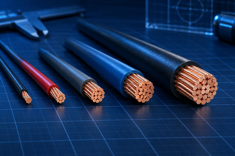
American Wire Gauge (AWG)
Diameters, cross-sectional areas, resistance and conversion formulas for sizing AWG conductors.
Written and technically reviewed byElectroDesignForge Engineering Team
View the editorial process📖 Definition
American Wire Gauge (AWG), defined by the ASTM B258 standard, is the conductor sizing system most widely used in North America.
It specifies the diameter, cross-sectional area, and main electrical characteristics of round conductors used in electrical and electronic applications.
Unlike the metric system, AWG uses a logarithmic scale: the lower the AWG number, the larger the conductor.
Quick reference
| Property | Value |
|---|---|
| Standard | ASTM B258 |
| System | American Wire Gauge |
| Range | 0000 AWG (4/0) → 40 AWG |
| Materials | Copper, aluminum |
| Reference temperature | 20 °C |
| Equivalent metric standard | IEC 60228 (approximate equivalence) |
Standard AWG table
| AWG | Diameter (mm) | Area (mm²) | IEC equivalent (mm²) | Copper resistance (Ω/km at 20 °C) | Typical current (A) |
|---|---|---|---|---|---|
| 30 | 0.255 | 0.0509 | — | 338.6 | 0.8 |
| 28 | 0.321 | 0.0810 | 0.08 | 212.9 | 1.4 |
| 26 | 0.405 | 0.129 | 0.14 | 133.9 | 2 |
| 24 | 0.511 | 0.205 | 0.20 | 84.2 | 3.5 |
| 22 | 0.644 | 0.326 | 0.34 | 53.0 | 7 |
| 20 | 0.812 | 0.518 | 0.50 | 33.3 | 11 |
| 18 | 1.024 | 0.823 | 0.75 | 20.9 | 16 |
| 17 | 1.150 | 1.04 | 1.00 | 16.5 | 19 |
| 16 | 1.291 | 1.31 | 1.50 | 13.2 | 22 |
| 14 | 1.628 | 2.08 | 2.50 | 8.29 | 32 |
| 12 | 2.053 | 3.31 | 4.00 | 5.21 | 41 |
| 10 | 2.588 | 5.26 | 6.00 | 3.28 | 55 |
| 8 | 3.264 | 8.37 | 10.00 | 2.06 | 73 |
| 6 | 4.115 | 13.30 | 16.00 | 1.30 | 95 |
| 4 | 5.189 | 21.15 | 25.00 | 0.815 | 125 |
| 2 | 6.544 | 33.63 | 35.00 | 0.513 | 170 |
| 1 | 7.348 | 42.41 | 50.00 | 0.407 | 195 |
| 1/0 | 8.252 | 53.49 | 50–53 | 0.323 | 230 |
| 2/0 | 9.266 | 67.43 | 70.00 | 0.256 | 265 |
| 3/0 | 10.404 | 85.03 | 95.00 | 0.203 | 310 |
| 4/0 | 11.684 | 107.20 | 120.00 | 0.161 | 360 |
The listed current ratings are approximate values for copper conductors installed in free air. Actual ampacity depends on insulation type, ambient temperature, installation method, and applicable standards.
AWG diameter formula
A conductor's diameter is defined by the logarithmic progression of the AWG system.
d(mm) = 0.127 × 92^((36 − AWG)/39)
Where:
| Symbol | Description |
|---|---|
| d | Conductor diameter (mm) |
| AWG | AWG size number |
Cross-sectional area
The cross-sectional area of a conductor is calculated from its diameter.
        π × d²
A = ───────────
            4
| Symbol | Description | Unit |
|---|---|---|
| A | Cross-sectional area | mm² |
| d | Diameter | mm |
Electrical resistance
A conductor's resistance depends on its material, length, and cross-sectional area.
        ρ × L
R = ───────────
          A
| Symbol | Description | Unit |
|---|---|---|
| R | Resistance | Ω |
| ρ | Electrical resistivity | Ω·m |
| L | Conductor length | m |
| A | Cross-sectional area | m² |
Practical example
A 10 m copper conductor using 18 AWG has:
- Diameter: 1.024 mm
- Cross-sectional area: 0.823 mm²
- Resistance: 20.9 Ω/km
Therefore:
R = 20.9 × 10 / 1000
R = 0.209 Ω
Bibliography
- ASTM B258 — Standard Specification for Standard Nominal Diameters and Cross-Sectional Areas of AWG Sizes of Solid Round Wires
- IEC 60228 — Conductors of insulated cables
- NEC (NFPA 70) — National Electrical Code
- IPC-2221 — Generic Standard on Printed Board Design
- UL 758 — Appliance Wiring Material