
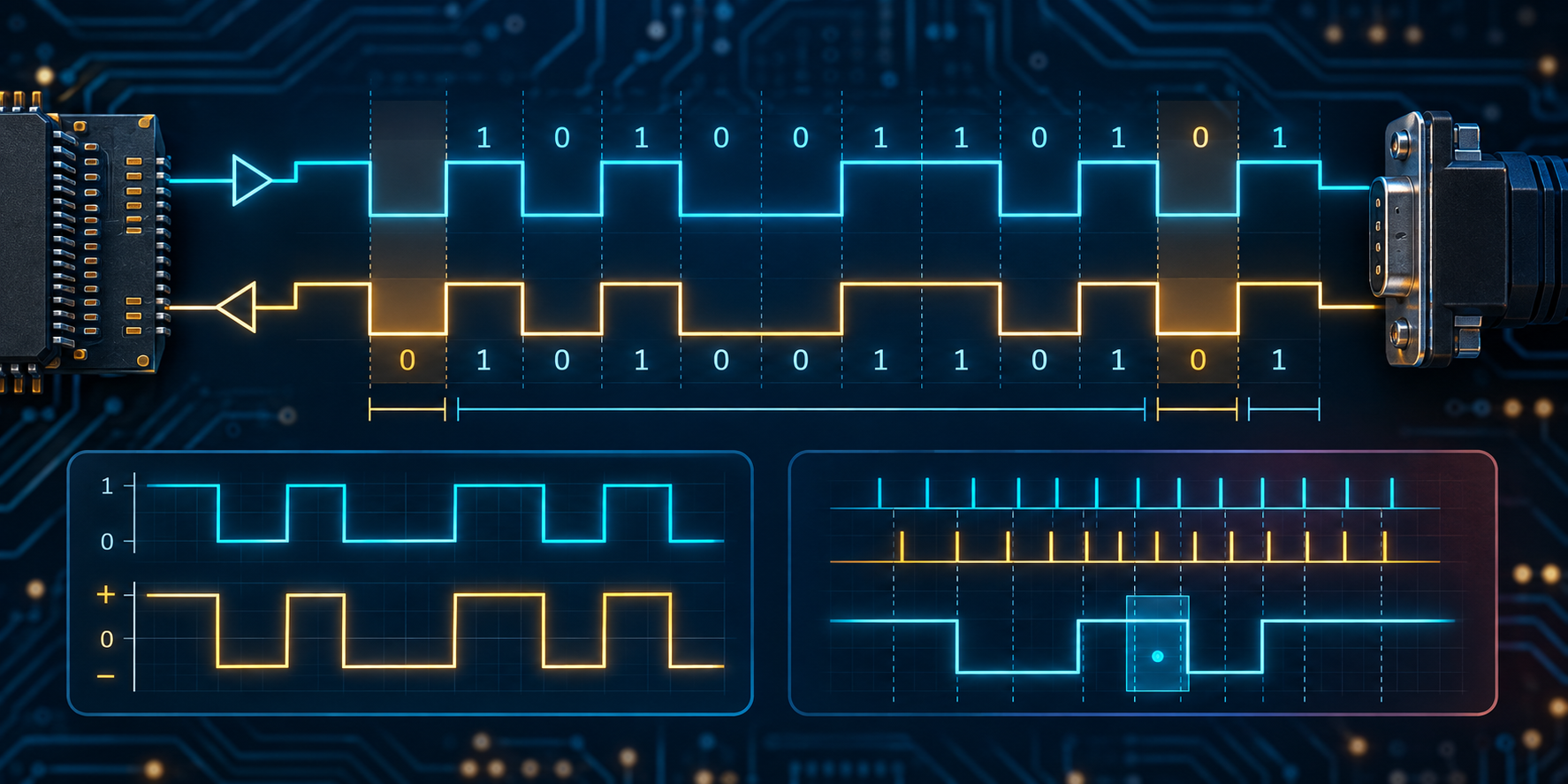
UART: frames, baud rate, and electrical levels
Understand asynchronous UART transmission: start and stop bits, data order, parity, baud rate, clock tolerance, errors, and TTL, CMOS, RS-232, and RS-485 compatibility.
Written and technically reviewed byElectroDesignForge Engineering Team
View the editorial processKey point: UART sends bits without a shared clock. The receiver re-synchronizes on each start bit, then samples data at calculated times. Both endpoints need the same frame format, sufficiently close baud timing, and truly compatible electrical levels.
UART is a frame format, not an electrical interface
UART (Universal Asynchronous Receiver/Transmitter) converts a byte into bits on TX and reconstructs received bytes on RX. It is asynchronous: unlike SPI, it has no clock wire.
| Layer | What it defines | Examples |
|---|---|---|
| UART frame | idle, start, data, parity, stop, bit order, rate | 8N1 at 115200 baud |
| Electrical link | voltage, polarity, reference, current, cable | 3.3 V CMOS, 5 V logic, RS-232, RS-485 |
Two boards can both “use UART” and still not connect directly: a 3.3 V GPIO is not an RS-232 output. In the usual logic convention, idle is high (mark), a frame begins low, and it ends high.
Frame anatomy
The usual notation is data bits + parity + stop bits. 8N1 means eight data bits, no parity, and one stop bit.
Idle        Start   D0 D1 D2 D3 D4 D5 D6 D7   Parity   Stop   Idle
  1     |     0   |  b0 b1 b2 b3 b4 b5 b6 b7 |   P    |  1  |  1
             <------------- one bit time Tb = 1 / baud ------------->
Start, data, parity, and stop
The start bit is low for one bit time. After a falling edge, the receiver waits roughly half a bit time to validate it, then samples near the centre of each cell. Modern UARTs often oversample at ×8 or ×16; consult the peripheral manual for the exact validation and tolerance.
Data is normally LSB-first. Hex 0x53, conventionally written 0101 0011, is sent as 1 1 0 0 1 0 1 0 for D0 through D7. This is an easy oscilloscope-reading trap. Hardware may offer 5 to 9 data bits; both endpoints must agree.
| Parity setting | Rule for data plus parity | Limitation |
|---|---|---|
N | no extra bit | no error detection |
E | total number of 1s is even | misses an even number of changed bits |
O | total number of 1s is odd | same detection ability, opposite convention |
| mark / space | forced 1 / forced 0 | uncommon hardware-specific modes |
Parity detects some corruption but cannot locate or repair it. Message integrity needs a CRC or checksum, sequence number, and retry scheme above UART. Stop bits are high; a low level when a stop bit is expected normally raises a framing error.
Baud rate and clock error
Baud is symbols per second. A binary UART normally carries one bit per symbol, so 9600 baud normally means 9600 bit/s. Bit time is Tb = 1 / baud.
| Rate | Tb | 8N1 frame time |
|---|---|---|
| 9,600 baud | 104.17 µs | 1.042 ms |
| 57,600 baud | 17.36 µs | 173.6 µs |
| 115,200 baud | 8.681 µs | 86.81 µs |
| 1,000,000 baud | 1.000 µs | 10.00 µs |
An 8N1 frame uses ten bit times, hence a maximum payload rate of baud × 8 / 10: continuous 115200-baud traffic carries at most 11,520 bytes/s before protocol overhead.
The transmitter and receiver have independent clocks. Their sampling offset accumulates across a frame: accumulated timing error ≈ number of bit intervals × total relative frequency error. Keep it comfortably below half a bit time, leaving margin for jitter, divider quantization, noise, and slow edges. A common engineering target is under about 2% combined relative error, but it is not a universal limit: frame length, oversampling, and receiver design decide the real tolerance. Two ±1% oscillators can differ by 2% at worst. Also check baud-divider error; a system clock does not always generate 115200 exactly.
CMOS, TTL, RS-232, and RS-485
“TTL” and “CMOS” are shorthand: always use the actual device’s input thresholds and absolute maximum ratings.
| Interface | UART idle | Typical voltages | Direct to 3.3 V UART? |
|---|---|---|---|
| 3.3 V CMOS | high | near 0 / 3.3 V | yes, if thresholds match |
| 5 V logic | high | near 0 / 5 V | only with 5 V-tolerant input |
| RS-232 | negative (mark) | often −5 to −12 V / +5 to +12 V | no, use an RS-232 transceiver |
| RS-485 | differential | A/B pair | no, use an RS-485 transceiver |
For a short logic link, wire TX_A to RX_B, TX_B to RX_A, and share a ground reference. A 5 V output can damage a non-tolerant 3.3 V input even if the link initially appears to work.
RS-232 uses both different amplitudes and inverted polarity: idle logic 1 is normally negative, start 0 positive. A MAX232-type transceiver handles voltage conversion and inversion. RS-485 is a differential physical layer, not “stronger UART”: the UART drives DI and reads RO, while the transceiver drives A/B. Enable control (DE), termination, biasing, cable topology, and half-duplex collision control are part of the design.
Errors and bring-up
| Indication | Usual meaning | Common causes |
|---|---|---|
| Parity error | received parity fails | noise, wrong setting, marginal timing |
| Framing error | stop bit invalid | wrong rate, inversion, break |
| Overrun | new byte arrived before handling the old one | blocked interrupt, missing DMA, small buffer |
| Break | line low longer than a frame | intentional break, short circuit, stopped device |
- Record the full setting: for example
115200, 8N1, LSB-first, no flow control, 3.3 V CMOS. - Check
TX ↔ RX, common ground, and transceiver power /DE. - Measure one cell: at 115200 baud it is about 8.68 µs.
- Send
0x55, then0x00and0xFFas diagnostic patterns. - Count parity, framing, and overrun flags; corrupt text alone does not identify the cause.
Common pitfalls
- Treating 115200 baud as 115200 bytes/s:
8N1tops out at 11,520 bytes/s. - Crossing TX/RX twice or omitting common ground on a CMOS link.
- Connecting RS-232 directly to GPIO.
- Using parity as message protection instead of a CRC.
- Blaming every error on baud rate when a full buffer, incompatible voltage, noisy ground, or RS-485 contention can look similar.