
Power over Ethernet (PoE): types, power, and cabling
Understand PSEs, PDs, detection, classification, Alternatives A/B, four-pair powering, and IEEE 802.3af, at, and bt power levels.
Written and technically reviewed byElectroDesignForge Engineering Team
View the editorial processKey point: PoE carries DC power and Ethernet data over the same twisted-pair cable. The PSE first detects a compatible device, negotiates a power class, and then powers the PD. To compare equipment, use the IEEE type, class, and power available at the PD, not a marketing label such as “PoE++”.
Quick reference
| Historical generation | IEEE type | Powered pairs | Maximum PSE power | Maximum power available at the PD |
|---|---|---|---|---|
| IEEE 802.3af | Type 1 | 2 | 15.4 W | 13 W |
| IEEE 802.3at | Type 2 | 2 | 30 W | 25.5 W |
| IEEE 802.3bt | Type 3 | 2 or 4 | 60 W | 51 W |
| IEEE 802.3bt | Type 4 | 4 | 90 W | 71.3 W |
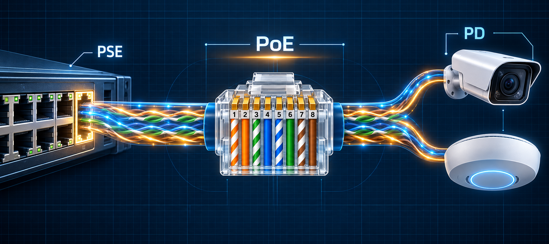
The PSE is the power source, such as a switch or injector. The PD is the powered device: a Wi-Fi access point, camera, phone, sensor, or controller. The difference between the last two columns accounts for the maximum permitted cable loss, among other factors.
802.3af, 802.3at, and 802.3bt are the historical amendment names most often printed on products. Their requirements are incorporated into the consolidated IEEE 802.3 standard.
PSE, PD, and PoE link startup
An endpoint PSE is built into a switch port. A midspan PSE, commonly called a PoE injector, sits between a non-PoE switch and the PD. In either case, an IEEE system follows a controlled sequence:
- Detection: the PSE applies a low test voltage and looks for the electrical signature of a valid PD.
- Classification: the PSE discovers the requested power and tells the PD how much it may draw.
- Inrush: current is limited while the PD input capacitors charge.
- Powering: the PSE monitors current, power, short circuits, and disconnection.
Detection prevents an IEEE PSE from applying its full voltage to an ordinary Ethernet device. A so-called passive PoE injector does not necessarily perform this check. Verify its voltage, polarity, and pin assignment separately because it can damage incompatible equipment.
Alternative A, Alternative B, and pin assignment
PoE groups the four pairs of the 8P8C connector into two pairsets. Mode and Alternative are used as synonyms in this context.
| PoE pairset | Pins | Data use with 10/100BASE-TX | Data use with 1000BASE-T and faster PHYs |
|---|---|---|---|
| Alternative A / Mode A | 1–2 and 3–6 | data pairs | data pairs |
| Alternative B / Mode B | 4–5 and 7–8 | unused for data | data pairs |
PoE Alternative A/B has no relationship to T568A/T568B. T568A and T568B assign wire colours to pins; the PoE alternatives identify the pairs that carry current.
With two-pair powering, the PSE uses one pairset. With four-pair powering, both pairsets participate. The two conductors in one pair have the same DC potential; the differential Ethernet signal is superimposed on this common-mode voltage and remains available through the port magnetics.
Do not assign one universal + or − sign to a pin in a generic diagram. Several polarity configurations are permitted, and a compliant PD must accept them through input rectification. See the Ethernet PoE pinout and RJ45 T568A/T568B pinout for pin-level views.
Types, classes, and pair count
The type defines the generation and broad capabilities. The class describes the negotiated power more precisely. A higher type number does not mean that every port automatically supplies the type maximum: supported class, per-port limit, and the switch’s total power budget still matter.
- Type 1 and Type 2 PSEs power over two pairs only.
- A two-pair-only Type 3 PSE can support up to Class 4, corresponding to a 25.5 W PD.
- A four-pair-capable Type 3 PSE can reach Class 6 and 51 W at the PD.
- A Type 4 PSE is four-pair capable and can reach Class 8 and 71.3 W at the PD.
- For Classes 1 through 4, a Type 3 or Type 4 PSE may use two or four pairs. Class 5 and above require four-pair powering.
The labels PoE, PoE+, and especially PoE++ are therefore insufficient for product selection. Depending on the vendor, “PoE++” may mean Type 3 or Type 4. Ask instead: which type, which class, and how much power is guaranteed at the PD?
Data and power share the pairs
10BASE-T and 100BASE-TX use pins 1–2 and 3–6 for data. Alternative B could therefore be described as power over the “spare pairs.” That wording becomes misleading with Gigabit Ethernet: 1000BASE-T, 2.5GBASE-T, 5GBASE-T, and 10GBASE-T use all four pairs for data.
PoE remains compatible with these rates because DC power is injected in common mode while data is differential. A Gigabit or multigigabit installation must nevertheless have all eight conductors and meet the required cable category. An old two-pair patch lead may establish a 10/100 link but is unsuitable for Gigabit and for all PoE configurations.
The Ethernet BASE-T speeds page lists pair count, cable category, and reach for each PHY.
Cable, distance, and heating
A standard copper channel generally reaches 100 m: up to 90 m of permanent link plus 10 m of combined equipment cords. This is a design limit, not a guarantee independent of temperature, conductor gauge, connectors, and cable bundling.
For a robust PoE installation:
- select a category that supports the data rate, then verify the cable and connectivity PoE ratings;
- use compliant solid-copper conductors, never copper-clad aluminium misrepresented as category cable;
- preserve pair twists to the termination and use all eight conductors;
- control loop resistance and DC resistance unbalance within and between pairs;
- follow manufacturer bundling, temperature, and derating rules, especially for Type 3 and Type 4;
- prefer a properly certified Cat 6A infrastructure for new high-power or multigigabit installations.
Current creates I²R loss. Excessive resistance reduces voltage at the PD and heats the bundle. Resistance unbalance distributes current unevenly and can also disturb Ethernet magnetics. A continuity test alone does not qualify a high-power PoE channel.
See Ethernet cable categories from Cat 5 to Cat 8 when selecting the medium.
Sizing a PoE system
- Record the PD’s maximum input power, not only its average consumption.
- Identify its type and class, then verify that the PSE supplies that class on the selected port.
- Check the switch’s total budget: twenty-four 30 W-capable ports do not necessarily mean 720 W are available simultaneously.
- Reserve margin for channel loss, temperature, startup, and intermediate accessories.
- Verify category, length, gauge, conductor material, and link certification.
- For a custom product, size the PD controller, rectification, isolation, DC/DC converter, and transient protection against the standard and component datasheets.
If the product advertises power through LLDP, do not assume this replaces electrical classification; both mechanisms can contribute to allocation. For troubleshooting, use a PoE tester that reports pairset, type, class, and loaded power capability instead of relying on an unloaded voltmeter reading.
Quick troubleshooting
| Symptom | Likely causes | Useful checks |
|---|---|---|
| No power | PD not detected, incompatible passive injector, disabled port, incomplete cable | PSE/PD type, all eight conductors, switch log, PoE tester |
| PD starts and then reboots | insufficient class, exhausted budget, voltage drop, inrush | negotiated power, actual load, channel length and resistance |
| Link is limited to 100 Mb/s | open pair, two-pair cord, poor termination | four-pair wiremap and link negotiation |
| Failures appear as more ports load | total budget or thermal limit reached | PSE budget, airflow, bundles, and temperature |
| Hot or intermittent connector | damaged contact, non-compliant cord, repeated disconnect under load | contact condition, certification, and cord replacement |
Related pages
- Ethernet PoE pinout — locate pairsets A and B on the eight pins.
- Ethernet RJ45 — T568A and T568B pinout — verify colours, pairs, and connector orientation.
- Straight-through and crossover Ethernet cables — understand terminations and auto-MDI-X.
- Ethernet cable categories from Cat 5 to Cat 8 — compare frequency, reach, and applications.
- Ethernet BASE-T speeds — connect rate, pair count, and minimum category.
Sources
- Ethernet Alliance — Overview of IEEE 802.3bt Power over Ethernet — types, classes, PSE/PD power, detection, pairsets, and polarity.
- IEEE Standards Association — IEEE 802.3bt-2018 — four-pair Power over Ethernet amendment.
- IEEE 802.3 — 4-Pair PoE Call for Interest — Alternatives A and B across the connector pins.
- Microchip Developer Help — PoE power interfaces — PSE, PD, midspan, and pairset terminology.
- Fluke Networks — DC resistance unbalance testing for PoE — resistance, heating, and non-compliant CCA conductors.