
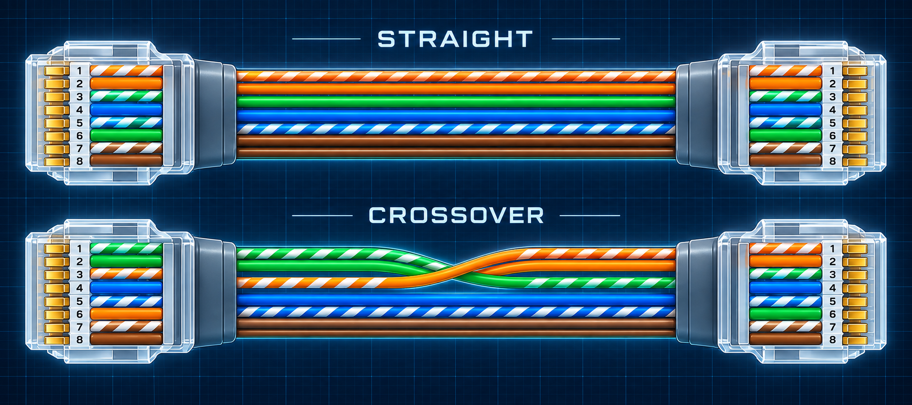
Straight-through and crossover Ethernet cables
Distinguish straight-through and crossover cables, T568A/T568B terminations, two- and four-pair crossover wiring, and Auto MDI-X.
Written and technically reviewed byElectroDesignForge Engineering Team
View the editorial processKey point: a straight-through cable uses the same termination at both ends: T568A–T568A or T568B–T568B. A traditional crossover cable uses T568A at one end and T568B at the other, crossing the two pairs used by 10BASE-T and 100BASE-TX. Modern Auto-MDI-X ports normally accept either cable, but legacy equipment may still require the correct type.
Straight-through, crossover, and termination scheme
T568A and T568B define how the four twisted pairs are assigned to the eight contacts of an 8P8C modular connector, commonly called RJ45. They do not define the Ethernet speed.
| End 1 | End 2 | Cable result | Practical meaning |
|---|---|---|---|
| T568A | T568A | Straight-through | Every pin reaches the same pin number |
| T568B | T568B | Straight-through | Every pin reaches the same pin number |
| T568A | T568B | Two-pair crossover | Orange and green pairs exchange positions |
| T568B | T568A | Two-pair crossover | Same electrical result in the opposite direction |
There is no Ethernet performance advantage to T568A or T568B. The important rule for a straight cable is to use one scheme consistently at both ends and to preserve each twisted pair. See the RJ45 T568A and T568B pinout for the complete colour order and connector orientation.
Straight-through cable
A straight-through cable connects pin 1 to pin 1, pin 2 to pin 2, and so on. It can be terminated A–A or B–B.
| End 1 pin | End 2 pin | Pair continuity |
|---|---|---|
| 1 | 1 | Pair on pins 1–2 |
| 2 | 2 | Pair on pins 1–2 |
| 3 | 3 | Pair on pins 3–6 |
| 4 | 4 | Pair on pins 4–5 |
| 5 | 5 | Pair on pins 4–5 |
| 6 | 6 | Pair on pins 3–6 |
| 7 | 7 | Pair on pins 7–8 |
| 8 | 8 | Pair on pins 7–8 |
Historically, a straight cable connected unlike port types: an MDI endpoint such as a computer or router to an MDI-X device such as a switch or hub. This remains the safest default when the capabilities of old equipment are unknown.
Traditional 10/100 crossover cable
10BASE-T and 100BASE-TX use two pairs: contacts 1–2 and 3–6. A T568A–T568B cable swaps these pair positions while preserving polarity within each pair.
| End 1 pin | End 2 pin | Result |
|---|---|---|
| 1 | 3 | Pair 1–2 crosses to pair 3–6 |
| 2 | 6 | Polarity is preserved |
| 3 | 1 | Pair 3–6 crosses to pair 1–2 |
| 6 | 2 | Polarity is preserved |
| 4 | 4 | Straight |
| 5 | 5 | Straight |
| 7 | 7 | Straight |
| 8 | 8 | Straight |
This cable was used between like legacy ports: computer-to-computer, router-to-router, switch-to-switch, or hub-to-hub. It is often called a half crossover because only two of the four pairs cross.
Do not identify a crossover cable from the jacket or connector colour. Compare the conductor order at both plugs or use a wire-map tester.
Four-pair crossover for legacy Gigabit equipment
1000BASE-T and faster copper Ethernet use all four pairs. A purpose-built four-pair crossover therefore also exchanges the pairs on pins 4–5 and 7–8.
| End 1 pin | End 2 pin |
|---|---|
| 1 | 3 |
| 2 | 6 |
| 3 | 1 |
| 6 | 2 |
| 4 | 7 |
| 5 | 8 |
| 7 | 4 |
| 8 | 5 |
A simple T568A–T568B cable does not make this full four-pair crossover: its blue and brown pairs remain straight. Four-pair crossover cables are now uncommon because Gigabit and newer equipment generally provides automatic pair correction. Use one only when the equipment documentation explicitly calls for it.
Auto-MDI-X
Auto-MDI-X lets a PHY detect the pair orientation required for the link and correct it internally. When both the speed mode and hardware support it, a straight-through or crossover cable can establish the same connection.
Do not assume this feature exists on every port. Older hubs, early switches, fixed-speed industrial devices, media converters, and ports with unusual forced settings may behave differently. If a link does not come up:
- Confirm that both ends support a common speed and duplex mode.
- Restore auto-negotiation unless the equipment manual requires fixed settings.
- Test the wire map, including split pairs and all eight conductors.
- Try the cable type specified by the manufacturer.
Common cabling faults
| Fault | Why it is a problem |
|---|---|
| A at one end and B at the other unintentionally | Creates a crossover instead of a straight cable |
| Correct pins but conductors from different pairs | Creates a split pair; continuity may pass while Ethernet fails |
| Excessive untwist at the plug or jack | Degrades crosstalk and return-loss performance |
| Only four conductors installed | May run 10/100, but prevents four-pair Ethernet and most modern PoE modes |
| Rolled or console cable | Reverses pin order and is not an Ethernet crossover cable |
| Couplers or patch panels terminated inconsistently | Can create a hidden crossover or pair fault in the channel |
A basic continuity tester proves conductor order, not high-frequency performance. Permanent links and channels should be certified to their declared category when bandwidth or PoE reliability matters.
PoE and crossover cables
Link operation alone does not prove that a cable is suitable for power. PoE also depends on all four pairs being correctly terminated, conductor resistance and balance, connector condition, and the supported IEEE power mode. Prefer standards-compliant straight-through structured cabling and verify unusual legacy crossover arrangements against the PSE and powered-device documentation.
See the Ethernet PoE pinout and the Power over Ethernet guide before applying power.
Related references
- RJ45 T568A and T568B pinout
- Ethernet cable categories: Cat 5 to Cat 8
- Ethernet BASE-T speeds
- Power over Ethernet (PoE)
Sources
- ANSI/TIA-568.2-E — Balanced Twisted-Pair Telecommunications Cabling and Components Standard — balanced-pair cabling, component performance, and T568A/T568B termination conventions.
- ISO/IEC 11801-1:2017 — Generic cabling for customer premises, Part 1: General requirements — generic balanced-cabling architecture and channel requirements.
- IEEE Std 802.3-2022 — IEEE Standard for Ethernet — twisted-pair Ethernet PHYs, MDI definitions, auto-negotiation, and powered MDI operation.
- Cisco — Configure and Verify Ethernet 10/100/1000Mb Half/Full Duplex Auto-Negotiation — straight-through, two-pair and four-pair crossover examples and Auto-MDI-X behaviour.