
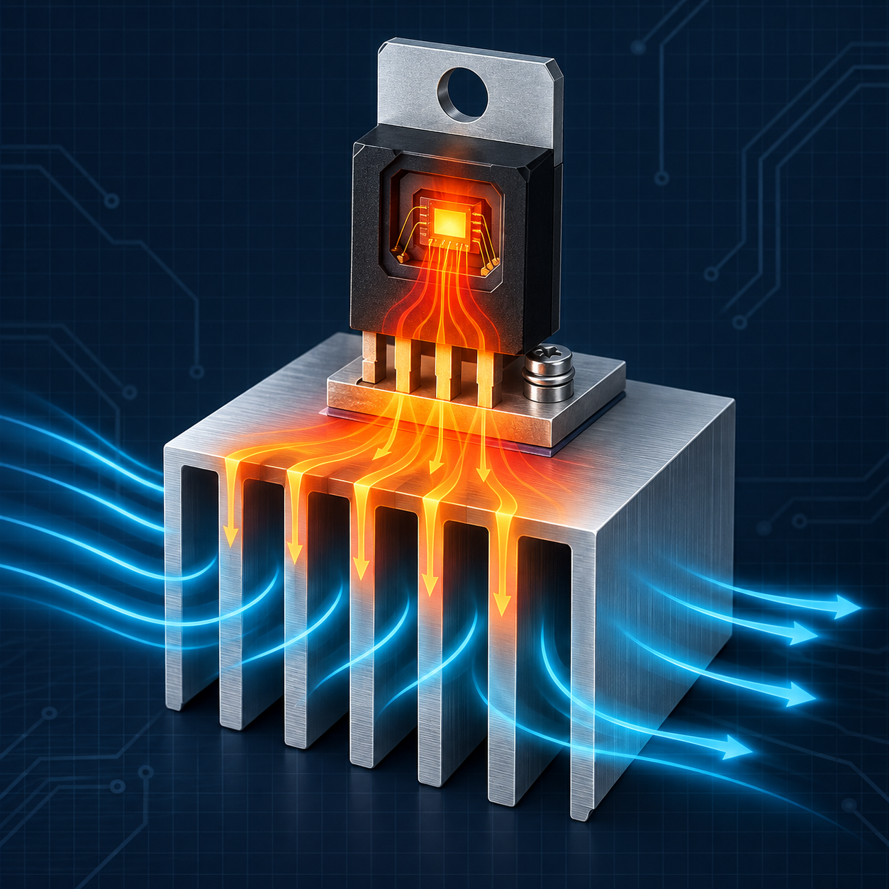
Junction temperature: thermal resistance and cooling
Calculate and interpret junction temperature with RθJA, RθJC, RθCS, and RθSA in still air, with airflow, or with a heatsink.
Written and technically reviewed byElectroDesignForge Engineering Team
View the editorial processKey point: junction temperature TJ is the temperature of the active region inside a semiconductor. At steady state, it is estimated from local ambient temperature, the power actually converted into heat, and the thermal resistance of the chosen path. This estimate is a sizing tool; it does not replace manufacturer curves, simulation, or measurement on the final product.
Quick reference
| Quantity | Symbol | Unit | Meaning in the tool |
|---|---|---|---|
| Local ambient temperature | TA | °C or °F | Air near the component or at the heatsink inlet |
| Junction temperature | TJ | °C or °F | Estimated temperature of the active die |
| Junction limit | TJ,max | °C or °F | Datasheet limit, not an operating target |
| Dissipated power | P | W or mW | Loss converted into heat inside the component |
| Junction-to-ambient resistance | RθJA | °C/W | Complete junction-to-air path under stated test conditions |
| Junction-to-case resistance | RθJC | °C/W | Junction to the defined case reference surface |
| Case-to-sink resistance | RθCS | °C/W | Interface material, insulation, contact, and mounting quality |
| Sink-to-ambient resistance | RθSA | °C/W | Heat rejection from the heatsink to air |
| Transient thermal impedance | Zθ(t) | °C/W | Time-dependent thermal response, not calculated by the tool |
For one steady-state thermal path:
ΔT = P × Rθeffective
TJ = TA + ΔT
Margin = TJ,max − TJ
One degree Celsius per watt and one kelvin per watt have the same numerical value for a temperature difference. Absolute Fahrenheit temperatures require the proper conversion, which the tool performs.
1. What junction temperature really represents
The junction is the silicon region where transistors and diodes dissipate power. It is inaccessible to an ordinary probe and can be substantially hotter than the visible package. For an integrated circuit, TJ is therefore neither ambient temperature nor top-of-package temperature.
Heat crosses several materials before reaching air: silicon, die attach, leadframe or substrate, package, PCB copper, thermal interface, and possibly a heatsink. Each stage resists heat flow, much as an electrical resistance resists current.
The analogy is useful:
| Electrical domain | Thermal domain |
|---|---|
| Voltage V | Temperature difference ΔT |
| Current I | Heat flow / dissipated power P |
| Resistance R | Thermal resistance Rθ |
| V = I × R | ΔT = P × Rθ |
This analogy describes an average budget. A die can contain several hot spots, nearby heat sources, and parallel paths that are invisible in a single-resistance model.
2. Dissipated power: enter loss, not useful throughput
The thermal calculation uses power that becomes heat inside the component being analysed. It can differ greatly from the electrical power passing through the circuit.
| Component | Starting estimate of dissipation |
|---|---|
| Linear regulator | P ≈ (Vin − Vout) × Iout + Vin × Iq |
| Conducting MOSFET | Pcond ≈ IRMS² × RDS(on), then add switching loss |
| Diode | P ≈ VF × Iaverage, plus dynamic loss where relevant |
| Switching converter | PIC is only part of Pin − Pout; external inductor, diode, and MOSFETs dissipate separately |
| Power resistor | P = IRMS²R = VRMS²/R |
Use the credible worst operating point: voltage, current, switching frequency, tolerances, and temperature. Average power may be suitable for a pulsed load if the thermal system reaches steady state; a short pulse requires Zθ(t) curves or a transient model.
3. Temperatures that must not be confused
TA: local ambient
TA is the air temperature receiving heat. Inside a sealed enclosure it may be far above room temperature. For a fan-cooled heatsink, use inlet air before it has been heated.
TC: case
TC is measured at a point defined by the manufacturer, often a metal face or the package centre. A different probe location may give a different result.
TS: heatsink
TS is the heatsink base temperature near the interface. Fins are normally cooler, so a measurement far from the base can underestimate the main-path temperature.
TJ,max: limit, not setpoint
The absolute maximum defines a boundary that must not be crossed. It does not guarantee electrical performance, accuracy, or lifetime near that boundary. A design needs margin for tolerances, transients, fouling, fan degradation, and interface ageing.
4. Understanding RθJA, RθJC, RθCS, and RθSA
RθJA is not a universal package constant
RθJA combines every path from junction to ambient during a standardised or manufacturer-defined test. In an exposed-pad package, much of the heat may flow into PCB copper instead of directly into air.
Its value depends on:
- copper area and thickness;
- thermal-via presence, diameter, and filling;
- layer count and internal planes;
- board and package orientation;
- air speed and direction;
- nearby components and internal product temperature.
A value measured on a JEDEC board does not automatically describe your PCB. Use it for a first estimate and look for manufacturer curves versus copper area or a documented evaluation-board layout.
RθJC describes a controlled path to the case
RθJC assumes heat is extracted through the designated case surface. It suits a heatsink chain when the assembly reproduces that path. Never add RθJA to RθJC: RθJA is already a complete path to ambient.
RθCS represents the interface
This resistance covers package-to-sink contact: flatness, pressure, area, grease, pad, electrical insulator, and thickness. A material’s typical number is only relevant at the intended thickness and pressure. Contact resistance can dominate with a small or poorly clamped surface.
RθSA depends on installation
Heatsink performance varies with orientation, air speed, obstructions, recirculation, and spacing. Use the manufacturer curve at the real airflow, not only a nominal value quoted under ideal conditions.
5. The calculator’s three modes
Still air: the RθJA path
Still air applies:
TJ = TA + P × RθJA
Choose it when there is no dedicated heatsink and you have an RθJA value representative of the PCB. It provides a steady-state order of magnitude.
Airflow: a screening model
When no manufacturer curve is available, the tool empirically separates a conduction-limited part from a convection part improved by airflow. With speed v converted to linear feet per minute (LFM):
Rθeffective = RθJA × [0.35 + 0.65 / (1 + 0.55 × √(vLFM / 100))]
1 m/s = 196.85 LFM
The 35% floor prevents infinite airflow from implying zero internal conduction resistance. This law is deliberately a comparison tool, not a universal physical property of the package. A manufacturer RθJA-versus-airflow curve, CFD model, or measurement always takes precedence.
Heatsink: detailed series chain
Heatsink adds the chosen path resistances:
Rθeffective = RθJC + RθCS + RθSA
TS = TA + P × RθSA
TC = TS + P × RθCS
TJ = TC + P × RθJC
The model assumes most heat follows this chain. In practice, some may also leave through pins and PCB; neglecting that parallel path is commonly conservative, but the exact geometry needs verification.
6. Reading every tool result
| Result | Calculation | Interpretation |
|---|---|---|
| Temperature rise ΔT | P × Rθeffective | Steady-state junction rise above ambient |
| Estimated TJ | TA + ΔT | Predicted internal temperature at the entered point |
| Margin | TJ,max − TJ | Reserve below the absolute limit |
| Maximum power at TA | (TJ,max − TA)/Rθ | Mathematical limit without design margin |
| Maximum TA | TJ,max − P × Rθ | Theoretical ambient at the limit for this power |
| Required maximum Rθ | (TJ,max − TA)/P | Total resistance that must not be exceeded |
| Thermal budget used | ΔT/(TJ,max − TA) | Fraction of available temperature rise consumed |
Comfortable margin means temperature is more than 10°C below TJ,max and less than 90% of the budget is used. Low margin appears within 10°C of the limit or at 90% budget use. Limit exceeded means the margin is negative. These thresholds are interface cues, not universal qualification rules.
In airflow mode the tool also shows equivalent TJ without airflow and estimated Rθ reduction. In heatsink mode it reports TS and TC, making comparison with measurements easier.
7. Package dimensions and surface power density
The optional dimensions calculate projected footprint:
A = length × width
Density = P / A
The tool expresses it in W/cm² and mW/mm². It helps compare components or flag concentrated dissipation, but it is not the true silicon power density: the active die is often much smaller than the package.
Do not derive temperature directly from this density. Two equal-area packages can have very different leadframes, exposed pads, and PCB heat paths.
8. Worked example: selecting a heatsink
A regulator dissipates 4 W in a cabinet where air may reach 50°C. Its limit is TJ,max = 150°C and its datasheet gives RθJC = 2°C/W. The selected interface is approximately RθCS = 0.5°C/W. We want 20°C margin, so TJ,target = 130°C.
Allowable total resistance with this margin is:
Rθtotal,target = (130 − 50) / 4 = 20°C/W
RθSA,max = 20 − 2 − 0.5 = 17.5°C/W
A heatsink rated at 12°C/W in the intended orientation gives:
Rθeffective = 2 + 0.5 + 12 = 14.5°C/W
ΔT = 4 × 14.5 = 58°C
TJ = 50 + 58 = 108°C
Margin below TJ,max = 42°C
TS = 50 + 4 × 12 = 98°C
TC = 98 + 4 × 0.5 = 100°C
The junction calculation looks comfortable, but the heatsink approaches 98°C: touch safety, nearby component temperature, and enclosure material must also be considered.
9. Thermal resistance Rθ versus Ψ parameters
Datasheets sometimes publish ΨJT or ΨJB. These are thermal characterisation parameters relating power to the junction-to-measurement-point difference in a given configuration. They can estimate TJ from measured top-of-package or board temperature:
TJ ≈ Ttop + ΨJT × P
ΨJT is not RθJC. Boundary conditions and heat-flow distribution differ. Using ΨJT in the RθJC + RθCS + RθSA chain can cause a substantial error.
10. Steady state and transients
The calculator assumes temperatures have stabilised. A component under a pulse does not instantly reach the temperature predicted by Rθ because thermal mass delays heating. The datasheet may give Zθ(t), sometimes normalised to Rθ, for a single or repetitive pulse calculation.
Conversely, final temperature may be underestimated when a test is stopped too soon. Wait for equilibrium or use a multi-time-constant thermal RC model.
The steady-state model does not capture:
- internal hot spots and non-uniform current sharing;
- power cycling and Zθ(t);
- dissipation changing with TJ;
- detailed radiation, recirculation, or mechanical conduction;
- mutual heating between components;
- thermal shutdown, foldback, or current limiting.
11. Designing for worst case
- Calculate credible maximum dissipation with electrical tolerances.
- Use maximum local ambient temperature, including enclosure self-heating.
- Use maximum thermal resistance or add margin to typical values.
- Check reduced airflow, clogged filters, and poor interface contact.
- Set a TJ,target below the absolute limit to suit reliability requirements.
- Analyse transients separately when power changes quickly.
- Validate operating corners on the assembled product.
RDS(on), leakage current, or forward voltage can change with temperature. If loss rises with TJ, recalculate iteratively until convergence and check for thermal runaway.
12. Measuring and validating a prototype
- Attach a very fine thermocouple at the recommended point with as little adhesive as practical.
- Correct emissivity when using an infrared camera; shiny metal commonly gives false readings.
- Measure TA without heating the probe through radiation or conduction from the board.
- Use ΨJT when the manufacturer supports junction estimation from top-of-package temperature.
- Where supported, an internal diode or temperature sensor gives a better junction estimate.
- Test in the final enclosure with real cables, covers, filters, orientation, and fans.
- Wait for stabilisation and repeat at extreme supply, load, and ambient conditions.
Common pitfalls
| Mistake | Consequence | Better practice |
|---|---|---|
| Entering load output power | Overstates or understates component heat | Calculate the component’s own loss |
| Using room temperature as TA | Ignores enclosure self-heating | Measure local air or sink inlet |
| Adding RθJA and RθJC | Counts incompatible paths | Use RθJA alone or JC + CS + SA |
| Confusing ΨJT with RθJC | Applies wrong boundary conditions | Use each parameter according to its definition |
| Targeting exactly TJ,max | Leaves no tolerance or transient reserve | Define a lower target temperature |
| Assuming airflow guarantees one Rθ everywhere | Ignores geometry and recirculation | Use a curve, CFD, or measurement |
| Applying Rθ at time zero | Ignores thermal inertia | Use Zθ(t) for pulses |
Associated tool
Open the Junction Temperature Calculator to compare still air, forced airflow, and a heatsink chain, then inspect margin, allowable power, and required thermal resistance.
Related guides
- Component temperature grades — distinguish operating, storage, ambient, and junction temperature ranges.
- Efficiency, losses, and battery life — calculate the power that becomes heat.
- PCB copper thickness and weight — understand an important part of the board heat path.
- MTBF versus service life — place thermal margin within a reliability process.
Sources
- JEDEC JESD51 — thermal measurement and characterisation methods for electronic packages.
- JEDEC JESD51-2A — natural-convection junction-to-ambient thermal resistance measurement.
- JEDEC JESD51-7 — test board for thermal measurements of surface-mounted packages.
- JEDEC JESD51-12 — guidance for reporting and using package thermal information.
- Datasheets and application notes for the selected component, thermal interface material, and heatsink.