
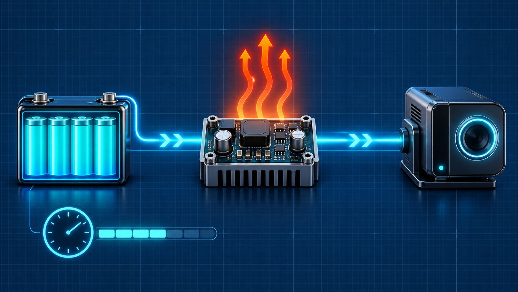
Efficiency, losses, and power budget
Build a battery-powered system power budget: input and output power, efficiency, thermal dissipation, available energy, and realistic runtime.
Written and technically reviewed byElectroDesignForge Engineering Team
View the editorial processKey point: a battery-powered product never receives all energy stored in its cell. At every stage, some power becomes heat or is consumed while idle. A power budget connects the useful load to input power, dissipation, and ultimately runtime.
Quick reference
| Quantity | Symbol | Unit | Role in the budget |
|---|---|---|---|
| Input power | Pin | W | Power drawn from the source or battery |
| Output power | Pout | W | Power actually delivered to the load |
| Efficiency | η | % or unitless | Fraction of Pin converted into Pout |
| Losses | Ploss | W | Power turned into heat or lost in the stage |
| Available energy | E | Wh | Total usable budget over time |
| Runtime | t | h | Time before the selected cutoff |
For a simple DC budget, use average powers:
P = V × I
η = Pout / Pin
Pin = Pout / η
Ploss = Pin − Pout = Pin × (1 − η)
E = P × t
t = E / P
Use efficiency as a value between 0 and 1 in equations: 90% = 0.90.
1. Input power, output power, and energy conservation
A converter, regulator, cable, or protection circuit does not create energy. It divides the drawn power between the useful load and losses:
Pin = Pout + Ploss
If a regulator supplies 5 V at 1 A, the load receives 5 W. With 90% efficiency at that operating point, the battery must supply more than 5 W:
Pout = 5 V × 1 A = 5 W
Pin = 5 W / 0.90 = 5.56 W
Ploss = 5.56 W − 5 W = 0.56 W
The 0.56 W does not vanish: here it becomes mainly heat in the regulator and its associated components. The battery therefore supplies 5.56 W, not 5 W.
Watch the voltage domains
Current is not conserved across a converter when input and output voltages differ. Compare power instead. A 12 V to 3.3 V buck that provides 1 A at the output delivers 3.3 W; at 90% efficiency, its idealised input current is about 0.306 A, not 1 A:
Pin = 3.3 W / 0.90 = 3.67 W
Iin = 3.67 W / 12 V = 0.306 A
For multiple rails, calculate each rail’s power first, then work backward stage by stage to the battery.
2. Calculate efficiency unambiguously
Efficiency compares useful output with total input:
η = Pout / Pin
η (%) = 100 × Pout / Pin
It is meaningful only at a defined operating point: input voltage, output voltage, current, control mode, temperature, and components. A datasheet may quote 95% at the peak of a curve while the product spends most of its time at 15 µA, where quiescent current dominates.
| Efficiency | Power lost per 1 W useful | Required input power |
|---|---|---|
| 95% | 52.6 mW | 1.053 W |
| 90% | 111 mW | 1.111 W |
| 80% | 250 mW | 1.250 W |
| 60% | 667 mW | 1.667 W |
Do not confuse efficiency with low absolute dissipation. At 95%, a 100 W stage still loses 5.26 W, often a major thermal concern.
3. Where losses come from
Mechanisms vary with architecture, but a budget should capture them even when a first calculation does not separate each one.
| Loss source | Typical relation or cause | Practical effect |
|---|---|---|
| Resistors, cables, and traces | P = I²R | Heating, voltage drop, and reduced peak margin |
| Linear regulator | Ploss ≈ (Vin − Vout) × Iout | Very costly when the voltage gap is large |
| Switching converter | Ploss = Pin − Pout | Switching, conduction, inductor, diode, and control losses |
| Quiescent current | Vin × Iq | Can dominate standby runtime |
| Protection and measurement | Drop in MOSFET, fuse, shunt, gauge circuit | Reduces available voltage and consumes energy |
| Battery | Internal resistance and self-discharge | Heating, voltage sag, energy inaccessible at cutoff |
A linear regulator is particularly easy to inspect. From 12 V to 5 V at 200 mA:
Pout = 5 V × 0.2 A = 1 W
Ploss = (12 V − 5 V) × 0.2 A = 1.4 W
η = 1 W / 2.4 W = 41.7%
It can be suitable at very low current, but a buck converter is generally required when the loss affects runtime or temperature.
4. Dissipation and temperature: the second budget
Lost power creates a temperature rise. As a first approximation:
ΔT ≈ Ploss × θJA
Tj ≈ Ta + ΔT
Here θJA is junction-to-ambient thermal resistance in the real PCB conditions, Ta is ambient temperature, and Tj is estimated junction temperature. The approximation is useful for scale, but θJA strongly depends on package, copper, thermal vias, airflow, and nearby components.
Example: a converter loses 0.8 W on a board with an estimated 45 °C/W effective thermal resistance. The approximate rise is 36 °C. At 40 °C ambient, junction temperature may therefore approach 76 °C before margins, peaks, or neighbour heating are considered.
Always verify maximum junction temperature, inductor and capacitor derating, and overload behaviour. The best runtime optimisation can also be a reliability improvement.
5. From battery energy to runtime
Ah is not directly an energy budget when voltage changes. Use watt-hours:
Enominal battery (Wh) ≈ Vnominal × capacity (Ah)
Eusable = Enominal battery × capacity factor × total efficiency × available margin
t ≈ Eusable / average load power
“Total efficiency” must include every stage crossed. With two stages at 92% then 90%:
ηtotal = 0.92 × 0.90 = 0.828 = 82.8%
Efficiencies multiply; they do not add. Other factors can represent capacity actually recoverable in the cold, ageing, self-discharge, and reserve held before cutoff.
Worked example: battery-powered sensor
A 3.7 V, 2 Ah battery stores approximately 7.4 Wh. The product averages 0.40 W on its useful rail. Assume 85% usable capacity at the target temperature, a 90% converter, and a 10% reserve before cutoff.
Eusable = 7.4 Wh × 0.85 × 0.90 × 0.90 = 5.09 Wh
t = 5.09 Wh / 0.40 W = 12.7 h
Dividing 2 Ah by load current can yield a very different result because it does not represent conversion, voltage variation, or reserves.
6. Build a usable power budget
Start with a table that distinguishes rails and operating states. Do not hide quiescent current or occasional loads in one average number.
| Stage / load | Voltage | Average current | Useful power | Efficiency or loss | Power seen upstream |
|---|---|---|---|---|---|
| MCU + sensors | 3.3 V | 30 mA | 99 mW | — | 99 mW |
| Radio, cycle average | 3.3 V | 60 mA | 198 mW | — | 198 mW |
| 3.3 V converter | — | — | 297 mW output | 88% | 338 mW input |
| Protection / gauge | 3.7 V | 2 mA | — | 7.4 mW | 7.4 mW |
| Battery | 3.7 V | — | — | — | about 345 mW |
The input power of one row becomes the useful output requirement of the preceding stage. For cyclic loads, calculate energy per cycle (Ecycle = P × duration) and divide by the complete cycle duration. This is safer than visually averaging widely separated currents.
7. Prototype verification method
- List every rail, converter, permanent load, and temporary operating state.
- Measure voltage and current at the correct point; convert to power before comparing different voltage domains.
- Read efficiency and quiescent current at real conditions, including the regulator’s sleep or burst mode.
- Add output powers, work back to the battery, and compare with battery current actually measured.
- Check peaks: average power predicts energy, but peak current and source impedance often decide brownout.
- Measure temperatures at high ambient and verify critical-component derating curves.
- Validate runtime on a representative cycle, at low temperature and with an aged cell or equivalent margin.
Common pitfalls
| Mistake | Why it skews the result | Correction |
|---|---|---|
| Adding currents from different rails | Their voltages differ. | Convert every load to watts first. |
| Using a datasheet’s peak efficiency | It is usually achieved at only one load point. | Read the curve at your Vin, Vout, and current. |
| Forgetting quiescent current | It acts continuously, even while the load sleeps. | Include Iq, gauge, LED, and leakage in the standby budget. |
| Estimating runtime from Ah / A | Battery voltage, conversion, and cutoff are ignored. | Work in Wh, then validate by test. |
| Checking only average power | A peak can collapse voltage before energy is exhausted. | Check peaks, ESR, wiring, and decoupling. |
| Treating dissipation as secondary | It changes efficiency, reliability, and current limits. | Make a thermal budget for critical stages. |
Associated tool
Open the Battery Life Calculator to split a cycle into multiple modes, identify dominant loads, and estimate runtime with actually available capacity.
Sources
- IEC 80000-6 — Quantities and units: electromagnetism.
- BIPM — The International System of Units (SI Brochure).
- Selected converter datasheet: efficiency curves, quiescent current, thermal limits, and test conditions.
- Cell datasheet: discharge curves, capacity versus temperature and current, internal impedance, and cutoff voltage.