
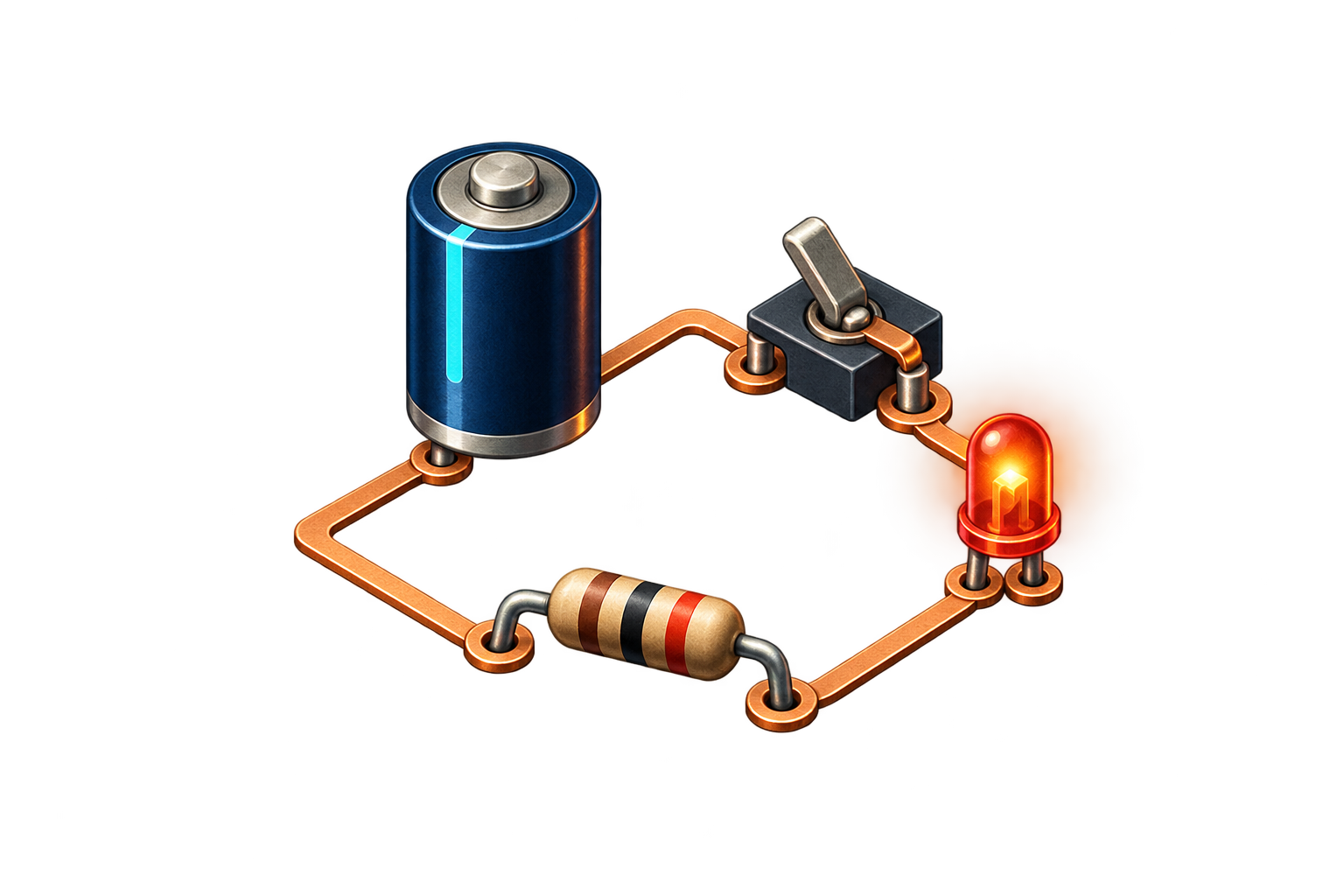
What does electronics do?
Electronics lets us move, control and use electrical energy. A lamp turns some of that energy into light; a sensor turns a physical quantity into a signal; a microcontroller processes the signal to decide what to do. The same basic idea appears in each case: connected components form a circuit.
A circuit is more than a collection of parts. A continuous conducting path is needed for steady current to flow. A battery may still have a voltage between its terminals when that path is broken. The next lessons will distinguish voltage, current and resistance more precisely.
Four roles to identify
- The source supplies energy and maintains a potential difference between its terminals, such as a battery or low-voltage power supply.
- Conductors connect the parts. These may be wires on a breadboard or copper traces on a circuit board.
- The load uses energy: an LED emits light, a motor turns, or a resistor warms slightly.
- The control opens or closes the path. An open switch stops current in that loop; a closed switch restores the path.
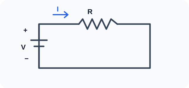
In this diagram, follow the path from the source's positive terminal, through the resistor, and back to the negative terminal. The arrow shows conventional current direction. Electrons move the other way in a metal conductor, but the convention is used when reading circuit diagrams.
Read a diagram before making connections
A circuit diagram describes electrical connections, not the physical positions of parts on a table. A line represents a connection; a component symbol indicates its function. Parts drawn far apart may be connected by the same line. Conversely, crossing lines are not necessarily connected: check the junction marks on the drawing.
Before applying power, look for a complete path and ask what happens when the switch opens. Also identify polarized parts: an LED must face the correct way.
A safe first experiment
Using two AA cells in series (about 3 V), a red LED and a 220 Ω resistor, make one loop: positive terminal → resistor → LED anode → cathode → negative terminal. The cathode is usually the shorter lead and the flat side of the LED body. Make connections with the cells disconnected, then power the circuit briefly to observe the LED. If it stays dark, disconnect power and check the connections and LED orientation.
The resistor limits current; do not connect the LED directly to the cells. Never short the battery terminals or use mains electricity for this experiment. You will calculate the current in the Ohm's law lesson.
Remember: identify the source, load and closed path, then compare the diagram with your real connections before applying power.