
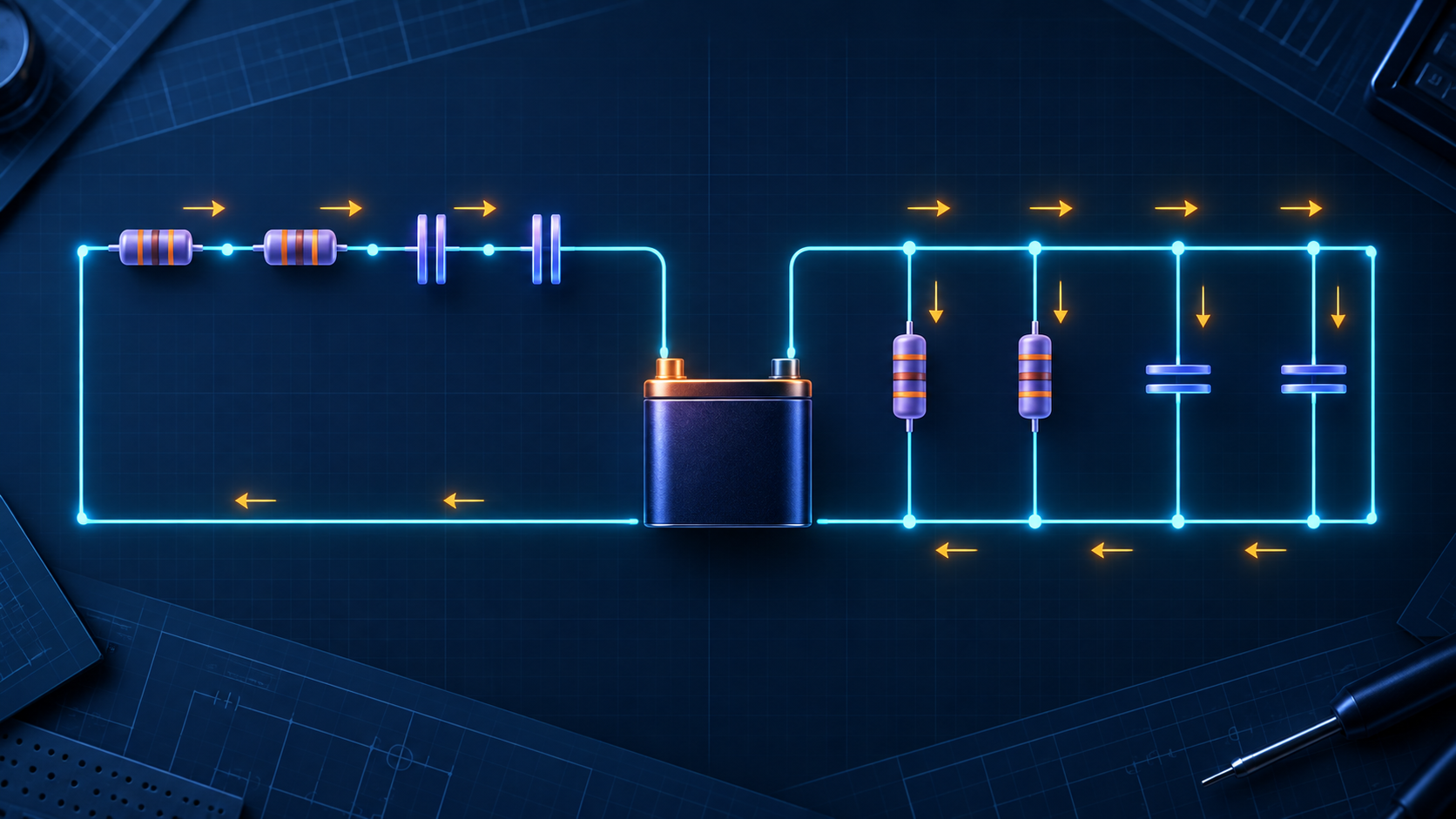
Series and parallel circuits: voltage, current, resistance, and capacitance
Determine voltage, current, and power sharing in series and parallel networks, then calculate their equivalent resistance and capacitance.
Written and technically reviewed byElectroDesignForge Engineering Team
View the editorial processKey point: in a series connection, the same current flows through every element and voltages divide. In a parallel connection, the same voltage is applied to every branch and currents divide. Resistance increases in series and decreases in parallel; capacitance does the opposite.
Quick reference
| Quantity | Resistors in series | Resistors in parallel | Capacitors in series | Capacitors in parallel |
|---|---|---|---|---|
| Voltage | divides | same across every branch | divides | same across every branch |
| Steady DC current | same | divides | ideally zero | ideally zero |
| Equivalent | R_eq = R₁ + R₂ + … | 1/R_eq = 1/R₁ + 1/R₂ + … | 1/C_eq = 1/C₁ + 1/C₂ + … | C_eq = C₁ + C₂ + … |
| Magnitude | greater than every R | less than the smallest R | less than the smallest C | greater than every C |
Network rules complement Ohm’s law, V = R × I: they identify which quantities are shared and which add. They assume ideal wiring and, unless stated otherwise, ideal components in DC steady state.
Identify nodes and branches first
Two components are in series only when the same current must pass through one and then the other, with no branch at the junction. Components are in parallel only when both of their terminals connect to the same two nodes, so their voltage is identical.
Series:       + ──[ R1 ]──[ R2 ]── −       same current I

Parallel:     + ──┬──[ R1 ]──┬── −          same voltage V
                 └──[ R2 ]──┘
Follow the electrical connections rather than the drawing layout. A continuous ideal wire is one node and therefore one voltage.
Resistor networks
Series resistors: current is shared
In a single path, current cannot split. For R₁, R₂, and R₃ in series:
I = I₁ = I₂ = I₃
R_eq = R₁ + R₂ + R₃
V_total = V₁ + V₂ + V₃
Each drop is Vₙ = I × Rₙ; the larger resistance receives the larger voltage share. This is the voltage-divider rule:
Vₙ = V_total × Rₙ / (R₁ + R₂ + …)
Worked example: voltage division and power
A 12 V source feeds R₁ = 1 kΩ and R₂ = 2 kΩ in series.
R_eq = 3 kΩ
I = 12 V / 3 kΩ = 4 mA
V₁ = 4 V
V₂ = 8 V
The check is 4 V + 8 V = 12 V. Resistor power is P = V × I, P = I² × R, or P = V² / R: R₁ dissipates 16 mW, R₂ dissipates 32 mW, and the source supplies 48 mW in total. Select the power rating with thermal margin, not just the calculated minimum.
Parallel resistors: voltage is shared
Every branch between the same two nodes has identical voltage:
V = V₁ = V₂ = V₃
I_total = I₁ + I₂ + I₃
Iₙ = V / Rₙ
1 / R_eq = 1 / R₁ + 1 / R₂ + …
For two resistors, R_eq = (R₁ × R₂) / (R₁ + R₂). Two equal R resistors give R/2; N equal resistors give R/N.
With 12 V across 1 kΩ and 2 kΩ, currents are 12 mA and 6 mA, so I_total = 18 mA and R_eq = 666.7 Ω. The lower-resistance branch carries more current and dissipates more power: 144 mW versus 72 mW. Current sharing is inversely proportional to resistance.
Tolerance and connected loads
Nominal values are not exact. Resistor tolerance changes divider ratios and branch currents. A load connected to a divider output is usually in parallel with its lower resistor, changing the equivalent resistance and reducing the output voltage. Analyse the complete network.
Capacitor networks
A capacitor stores charge, Q = C × V, and energy, E = ½ × C × V². Capacitance is measured in farads, commonly µF, nF, or pF. After charging in DC, an ideal capacitor carries no current; during a transient or in AC its behaviour depends on frequency and impedance.
Parallel capacitors: capacitance adds
Parallel capacitors have the same voltage and their stored charges add:
V = V₁ = V₂ = …
Q_total = Q₁ + Q₂ + …
C_eq = C₁ + C₂ + …
For example, 10 µF in parallel with 22 µF gives 32 µF. The association increases charge storage and ideally reduces high-frequency impedance, although ESR, ESL, and PCB layout limit the practical result.
Series capacitors: charge is shared
In an isolated series chain, every capacitor carries the same charge:
Q = Q₁ = Q₂ = …
1 / C_eq = 1 / C₁ + 1 / C₂ + …
Voltage is Vₙ = Q / Cₙ, so the smaller capacitor receives the larger voltage. Two identical capacitors C have an equivalent value of C/2 and ideally split the applied voltage equally.
Worked example: two unequal capacitors
Put C₁ = 10 µF and C₂ = 20 µF in series across 12 V:
C_eq = (10 × 20) / (10 + 20) µF = 6.67 µF
Q = C_eq × V = 80 µC
V₁ = Q / C₁ = 8 V
V₂ = Q / C₂ = 4 V
8 V + 4 V = 12 V. Do not apply that ideal split blindly to real series capacitors: leakage, tolerance, bias, and temperature shift the voltages. For polarized capacitors in a high-voltage series stack, provide balancing resistors where manufacturer guidance calls for them.
Capacitor current and power
Instantaneous capacitor current is i = C × dV/dt. More capacitance needs more current for the same voltage change in the same time. In AC, capacitive reactance is:
X_C = 1 / (2πfC)
Greater capacitance or frequency reduces X_C. An ideal capacitor consumes no average real power, but ESR creates heat: approximately P_ESR = I_RMS² × ESR. Check ripple-current rating, ESR, voltage rating, and capacitance drift as well as the µF value.
Power-balance check
With passive sign convention, resistors absorb positive power and a source delivering energy has negative algebraic power. A valid result satisfies:
Σ P = 0
Sum the branch powers of a resistive network and compare them with V_source × I_source. A mismatch commonly exposes a branch, unit, or applied-voltage error. Reduce only groups that are truly series or parallel; use Kirchhoff’s laws for the remainder.
Reliable workflow
- Mark the two nodes of every candidate group.
- Reduce the simplest true series or parallel groups one step at a time.
- Calculate total current or source voltage from the equivalent.
- Expand back: series gives individual voltages; parallel gives individual currents.
- Check each resistor’s power. For capacitors, check voltage per component, stored energy, ESR, and ripple current.
Common mistakes
- Adding parallel resistances or series capacitances: their formulas are reciprocal.
- Calling components series merely because they are drawn in a line, even though another branch exists at their junction.
- Dividing voltage equally across unequal resistors or capacitors.
- Using total network power as the rating for each individual resistor.
- Ignoring divider loading or real capacitor voltage balancing.
Associated calculators
- Open the Resistor network calculator for series/parallel combinations, equivalent resistance, voltage sharing, tolerance, and power.
- Open the Capacitor network calculator for equivalent capacitance, charge, energy, and connection rules.
Sources
- IEC 80000-6 — Quantities and units: electromagnetism.
- C. K. Alexander and M. N. O. Sadiku, Fundamentals of Electric Circuits.
- Capacitor-manufacturer application notes on series connection, ESR, and ripple current.