
Sampling, Nyquist frequency, and aliasing
Size an ADC sampling rate, identify spectral folding, and select a realistic anti-aliasing filter while accounting for its transition band.
Written and technically reviewed byElectroDesignForge Engineering Team
View the editorial processKey point: an ADC does not observe a signal continuously; it takes values spaced by
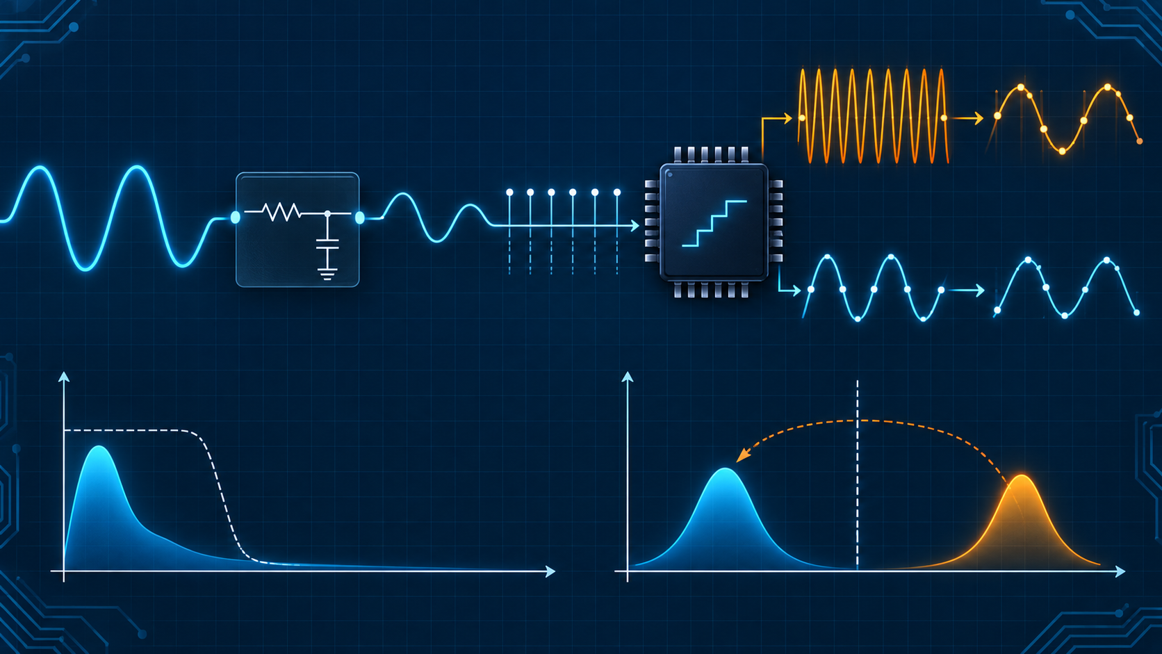
T_s = 1 / f_s. To reconstruct a signal limited tof_maxwithout ambiguity, ideally usef_s > 2 × f_max. Thisf_s / 2limit is the Nyquist frequency. Energy above it folds into the useful band: aliasing. An analog filter before the ADC is therefore part of the conversion system, not an optional accessory.
Quick reference
| Quantity | Relation | Practical role |
|---|---|---|
| Sampling period | T_s = 1 / f_s | time between conversions |
| Sampling frequency | f_s = 1 / T_s | samples per second |
| Nyquist frequency | f_N = f_s / 2 | upper limit of the representable band |
| Ideal condition | f_s > 2 × f_max | valid for a strictly band-limited signal |
| Folding | `f_alias = | f_in − k × f_s |
Use the integer k that places f_alias between 0 and f_s/2; several input frequencies can then yield the same alias. The ADC cannot tell them apart.
What an ADC actually does
A typical acquisition chain is:
sensor / source → protection and conditioning → anti-alias filter → sample-and-hold → ADC → digital processing
At every nT_s, the sample-and-hold captures a voltage and holds it long enough for conversion. Conversion also adds quantization into code levels: that creates quantization noise/error, but it does not cause aliasing. Aliasing is caused by discrete time: a sampled signal’s spectrum repeats every f_s.
A real ADC has further limits: acquisition time, switched input capacitance, maximum source impedance, conversion time, clock jitter, and voltage range. The selected data rate must therefore be achievable and stable with the analog front end.
Nyquist–Shannon: condition and scope
The Nyquist–Shannon theorem says a signal strictly limited in bandwidth below f_s/2 can, in theory, be reconstructed from its samples. It does not say that two samples per cycle make a robust measurement.
At f_s = 2 × f_max, there is no available transition band for the filter. A sine wave near Nyquist also has only two points per cycle, making phase and amplitude sensitive to clock error, noise, and filter imperfections. In practice, select a higher f_s to reserve a zone between the useful band and Nyquist.
Example: a measurement must preserve 0 to 20 kHz. At f_s = 48 kS/s, f_N = 24 kHz, so the filter transition is only 4 kHz. At f_s = 96 kS/s, Nyquist rises to 48 kHz: the filter can pass 20 kHz and attenuate interference before 48 kHz, a much more practical design.
Spectral folding explained
When sampled, a component at f_in and one at f_s − f_in produce the same sequence of values, apart from phase or inversion. The observed result is a lower frequency that may not exist in the original signal.
Folding example
Sample at f_s = 10 kS/s:
f_N = 5 kHz
f_in = 6.2 kHz
f_alias = |6.2 − 1 × 10| = 3.8 kHz
A real 6.2 kHz disturbance therefore appears in data as a 3.8 kHz tone. Increasing ADC resolution does not fix it: the false tone has already entered the digital band. Once folded, its energy overlaps the desired signal; no later digital filter can separate them.
Harmonics, broadband noise, supply switching, and RF emissions can fold too. In a slow temperature measurement, for example, a kilohertz-range disturbance can become a drift or a very-low-frequency ripple after sampling.
The anti-alias filter: analog protection
An anti-alias filter is an analog, usually low-pass, filter before the sampler. Its purpose is not to remove every frequency above the useful band—that is unrealistic. It must sufficiently reduce components that would fold so they remain below the measurement’s error, noise, or dynamic-range budget.
Define four quantities:
f_pass: maximum useful frequency, with allowed ripple/gain error.f_stop: first frequency that can fold into the band of interest; for a baseband measurement it is often close tof_s − f_pass.A_pass: maximum allowed loss in the useful band.A_stop: required attenuation in the stop band.
For a 0–20 kHz measurement at 48 kS/s, components from 28 kHz = 48 − 20 can fold below 20 kHz. The filter must transition between 20 and 28 kHz—not merely between 20 and 24 kHz. That distinction is essential in a filter specification.
How much attenuation is enough?
Derive attenuation from the disturbance level before the filter and its tolerated level after folding. If a worst-case 1 V_RMS interferer at a dangerous frequency must become less than 1 mV_RMS, at least this is needed:
A_stop = 20 × log10(1 V / 1 mV) = 60 dB
Add margin for component tolerance, sensor gain, resonances, out-of-band noise, and temperature. Also check overload: a large out-of-band signal can saturate the amplifier or ADC input before it is sufficiently attenuated.
Order, slope, and cutoff frequency
A first-order low-pass attenuates asymptotically at 20 dB/decade or 6 dB/octave. Its cutoff is:
f_c = 1 / (2πRC)
It is often excellent for limiting noise and isolating a source from the sampled input, but its rejection close to Nyquist may be insufficient. Multiple poles, an active filter (Sallen–Key or multiple feedback), or a switched-capacitor filter provide a steeper slope. The tradeoffs are tolerance, noise, drift, phase, consumption, and sometimes load sensitivity.
Do not confuse f_c with the frequency where required attenuation is reached. A first-order filter is only −3 dB at cutoff. Use the RC and RL filter calculator to explore R, C, load, and cutoff, then verify attenuation at every risky frequency.
Oversampling and decimation
Oversampling means selecting an f_s well above the final required data rate. It moves Nyquist away from the useful band, widens the analog filter transition region, and makes anti-aliasing easier. Samples can then pass through a digital filter and be decimated.
The digital filter is after the first ADC, however: it protects only the decimation operation. The ADC input still needs analog filtering against frequencies above its first Nyquist limit. Sigma-delta ADCs use extensive oversampling and internal decimation; read their output rate, useful bandwidth, and digital-filter response carefully.
Clock jitter and high-frequency inputs
The sampling instant is never perfectly fixed. RMS timing uncertainty t_j limits jitter-related signal-to-noise ratio:
SNR_jitter ≈ −20 × log10(2π × f_in × t_j)
The limit gets worse as f_in increases. With t_j = 10 ps and a 10 MHz sine wave, theoretical SNR from jitter alone is about 64 dB. An ideal 16-bit ADC has about 98 dB quantization SNR, so clock, ADC driver, and routing quality can limit the measurement long before the advertised bit count.
A reliable sizing workflow
- List the useful band, maximum signal, noise sources, and plausible interference.
- Set the final data rate and choose
f_swith transition-band margin, not only2 × f_max. - Calculate frequencies that can fold into the useful band:
f_s ± f_signal, then multiples where needed. - Convert the error budget into required attenuation at those frequencies.
- Choose filter topology and order, then check gain, phase, noise, overload, and impedance seen by the ADC.
- Read the datasheet: acquisition time, permitted source resistance, recommended input network, and clock requirements.
- Test the complete system with out-of-band tones and an FFT; include temperature and tolerance corners.
Common pitfalls
- Setting
f_s = 2f_maxwith no transition-band allowance. - Putting the filter after the ADC and expecting it to correct aliasing: the damage is already irreversible.
- Setting cutoff at
f_Ninstead of finding the first band that folds into the useful band. - Forgetting harmonics, broadband noise, and switching transients.
- Ignoring the ADC loading network: a source that is too resistive may not charge the internal capacitor during acquisition.
- Assuming extra bits or digital averaging remove a coherent aliased tone.
Associated tools
- Open the ADC/DAC calculator to convert voltage, code, LSB, and quantized values.
- Open the RC and RL filter calculator to pre-size an analog cutoff and evaluate load effects.
Sources
- C. E. Shannon, Communication in the Presence of Noise; H. Nyquist’s foundational signal-transmission work.
- IEEE 1241, Standard for Terminology and Test Methods for Analog-to-Digital Converters.
- ADC datasheets and application notes covering acquisition time, input networks, and filtering guidance.