
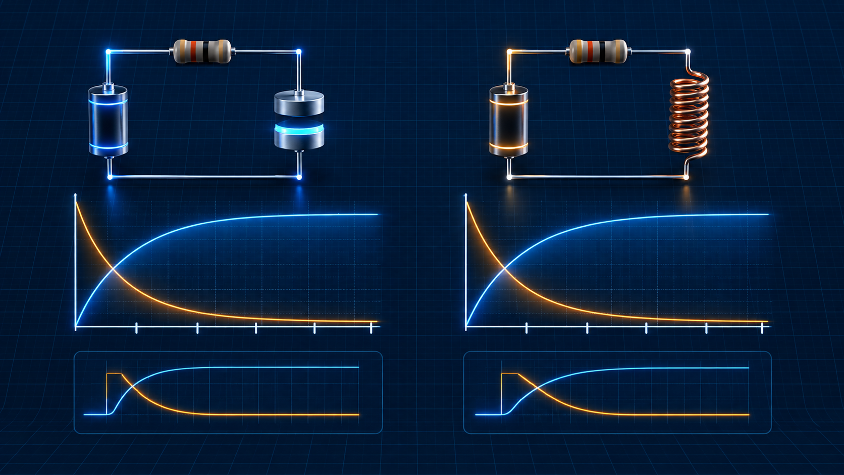
RC and RL time constants: charging, discharging, and transients
Calculate the time constant τ of RC and RL circuits, interpret charging, discharging, and transient response, then apply the 5τ rule correctly.
Written and technically reviewed byElectroDesignForge Engineering Team
View the editorial processKey point: the time constant
τmeasures how quickly a first-order circuit responds. For RC,τ = R × C; for RL,τ = L / R. After1τ, the response has travelled 63.2% of the way to its final value; after5τ, only about 0.67% of that difference remains. The circuit is usually treated as settled, although it is never mathematically instantaneous.
Quick reference
| Circuit | Time constant | Ideally continuous quantity | Step response | At 5τ |
|---|---|---|---|---|
| Series RC | τ = R × C | capacitor voltage V_C | V_C rises or falls exponentially | 99.33% of the change completed |
| Series RL | τ = L / R | inductor current I_L | I_L rises or falls exponentially | 99.33% of the change completed |
Use SI units: R in ohms (Ω), C in farads (F), L in henrys (H), and τ in seconds (s). Thus, 10 kΩ × 100 nF = 1 ms and 10 mH / 10 Ω = 1 ms.
Transients: the difference from the final state decays
A transient is the interval between two steady states, such as immediately after a switch closes. A capacitor opposes an instantaneous change in voltage; an inductor opposes an instantaneous change in current:
V_C(0+) = V_C(0−) I_L(0+) = I_L(0−)
This does not mean capacitor current or inductor voltage stays constant: both can be large at the start. The general expression for a quantity x moving to a final value is:
x(t) = x_final + [x(0+) − x_final] × e^(−t/τ)
It covers charging and discharging. Every τ, the difference from the final value is divided by e. Source resistance, ESR, winding resistance, and supply limitation set real peaks.
RC: capacitor charging
With a source V_S, resistor R, and initially discharged capacitor C:
+V_S ──[ R ]───┬──
               │
              [ C ]
               │
0 V ───────────┴──

τ = R × C
V_C(t) = V_S × (1 − e^(−t/τ))
I(t) = (V_S / R) × e^(−t/τ)
Initially, V_C = 0 and ideal current is V_S / R; at steady state, V_C approaches V_S and current approaches zero. Final stored energy is E = ½ × C × V_S².
RC example
For V_S = 12 V, R = 10 kΩ, and C = 100 nF:
τ = 10,000 Ω × 100 × 10⁻9 F = 1 ms
V_C(1 ms) = 12 V × (1 − e⁻¹) = 7.59 V
I(0+) = 12 V / 10 kΩ = 1.2 mA
After roughly 5 ms, the capacitor reaches 11.92 V. This sizes a delay, but a logic circuit can become usable before 5τ as soon as it crosses its real threshold.
RC discharge and bleed resistor
If a capacitor initially at V_0 discharges through R toward 0 V:
V_C(t) = V_0 × e^(−t/τ)
I(t) = −(V_0 / R) × e^(−t/τ)
Use the general formula for a non-zero final voltage. For a target voltage during a zero-volt discharge:
t = −τ × ln(V_target / V_0)
Example: 470 µF at 24 V must fall below 5 V through 10 kΩ. τ = 4.7 s and t = −4.7 × ln(5/24) = 7.37 s. Initial resistor dissipation is 24² / 10 kΩ = 57.6 mW; check power, energy, and voltage rating.
RL: current build-up
In a series R-L circuit driven by V_S, the inductor slows current build-up. Its voltage is V_L = L × dI/dt:
+V_S ──[ R ]──( L )── 0 V

τ = L / R
I_L(t) = (V_S / R) × (1 − e^(−t/τ))
V_L(t) = V_S × e^(−t/τ)
At t = 0+, the inductor carries nearly the whole source voltage and current is zero. At DC steady state, an ideal inductor is a short circuit and current tends to V_S/R. For τ, use the resistance seen by the inductor with independent sources zeroed, including source, winding, and series-load resistance.
RL example
With L = 10 mH, total resistance R = 10 Ω, and V_S = 5 V:
τ = 10 mH / 10 Ω = 1 ms
I_final = 5 V / 10 Ω = 0.5 A
I_L(1 ms) = 0.5 A × 0.632 = 0.316 A
Include winding resistance. Omitting it overestimates τ and can underestimate final current or dissipation.
RL current decay and turn-off overvoltage
When a switch opens, inductor current must remain continuous. The coil generates the voltage needed to find a path; without a freewheel path, it may damage a transistor, switch, or insulation. A flyback diode reduces overvoltage but extends turn-off because it limits coil voltage. A diode plus Zener/TVS or a snubber can balance protection, speed, and EMC.
Initial stored energy is E = ½ × L × I_0²; it must be dissipated in a resistor, diode, TVS, arc, or another path.
The 5τ rule, precisely
The completed fraction of a rise after nτ is 1 − e^(−n); the remaining fraction of a decay is e^(−n).
| Time | Rise completed | Difference remaining |
|---|---|---|
1τ | 63.2% | 36.8% |
2τ | 86.5% | 13.5% |
3τ | 95.0% | 5.0% |
4τ | 98.2% | 1.8% |
5τ | 99.3% | 0.67% |
5τ is a design convention, not a physical boundary. A precise timer can need more margin when R and C have tolerance, capacitance shifts with bias/temperature, or a threshold is near the final value. Conversely, a digital function can be available before 5τ.
Reliable calculation workflow
- Set conditions before and immediately after switching (
V_C(0+)orI_L(0+)). - Determine the final DC value.
- Find equivalent resistance seen by the reactive element; zero independent sources only to calculate
τ. - Use
τ = R_eq × Cfor RC orτ = L / R_eqfor RL. - Check voltage, current, energy, and initial power with the general expression.
Common pitfalls
- Forgetting source resistance, load, ESR, or winding resistance.
- Treating a circuit as exactly finished at 5τ: its response remains asymptotic.
- Confusing an ideal capacitor’s steady DC current (zero) with initial charging current.
- Forgetting the current path when an inductor turns off.
- Applying first-order equations to several independent reactive elements without reduction or simulation.
Associated calculators
- Open the RC and RL filter calculator to connect
R,C, orLwith cutoff frequency, load, and filter behaviour. - Open the capacitor charge calculator to size RC precharge, visualise voltage and current, and check safe discharge.
Sources
- IEC 80000-6 — Quantities and units: electromagnetism.
- C. K. Alexander and M. N. O. Sadiku, Fundamentals of Electric Circuits.
- Application notes on RC/RL transients, relay drive, and flyback diodes.