
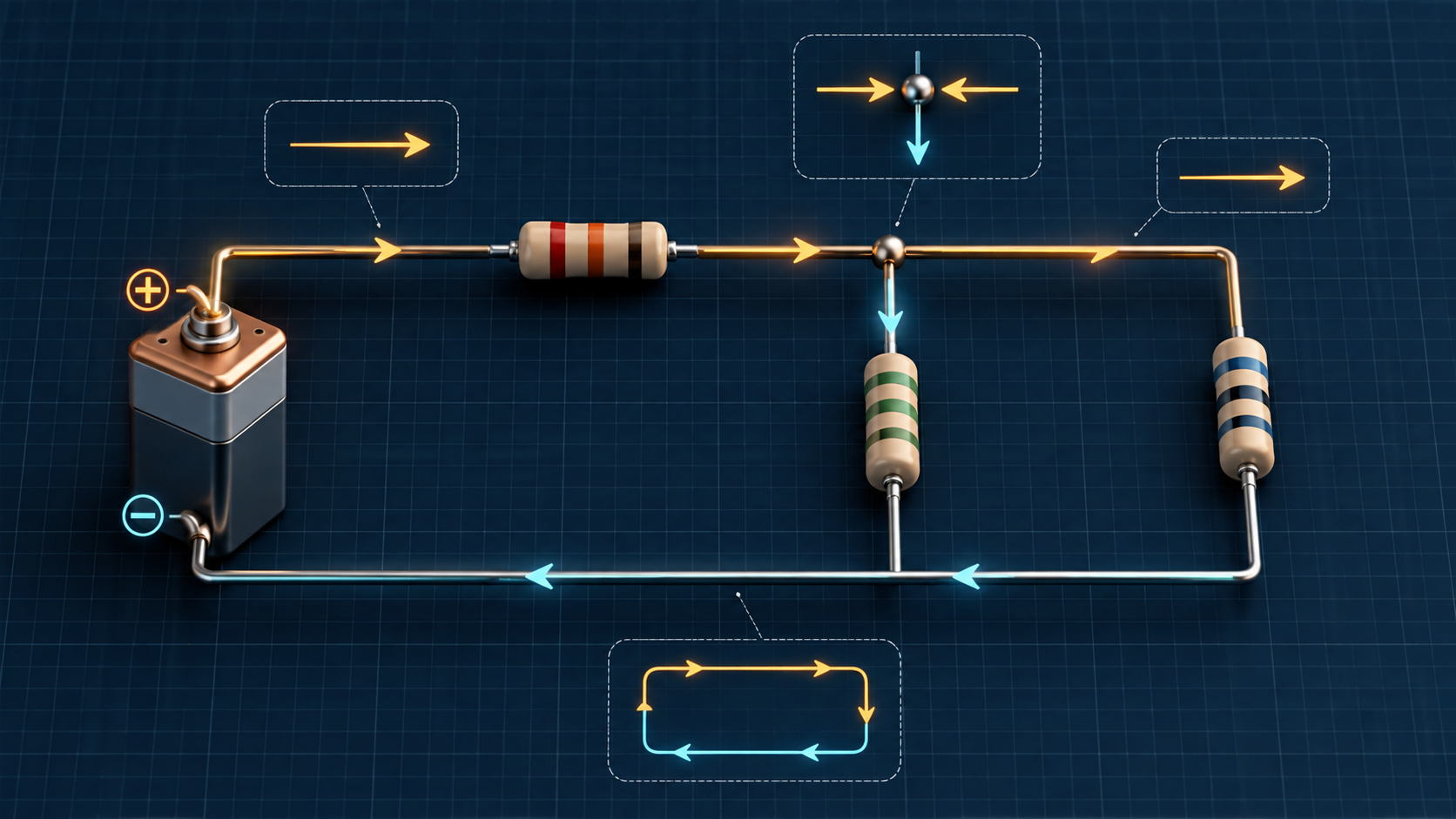
Kirchhoff’s laws: nodal and mesh analysis
Apply Kirchhoff’s current law (KCL) and voltage law (KVL), choose consistent sign conventions, and solve resistive circuits step by step.
Written and technically reviewed byElectroDesignForge Engineering Team
View the editorial processKey point: Kirchhoff’s current law (KCL) conserves current at every junction. Kirchhoff’s voltage law (KVL) makes the algebraic sum of voltages around every closed loop zero. Choose a sign convention once and keep it throughout the calculation.
Quick reference
| Law | Equation | Physical idea | Associated method |
|---|---|---|---|
| Kirchhoff’s current law — KCL | Σ I = 0 | Charge does not accumulate at an ideal node | Nodal analysis |
| Kirchhoff’s voltage law — KVL | Σ V = 0 | Energy per unit charge is conserved around a closed loop | Mesh analysis |
A node is a set of points joined by ideal conductors. A branch joins two nodes and contains one or more elements. A mesh is a closed loop that contains no other loop.
These laws apply to usual lumped circuits. In a loop exposed to significant time-varying magnetic flux, induced voltage must be included; the simple Σ V = 0 form alone is then insufficient.
Sign conventions: the rule that prevents errors
You may choose current directions and voltage polarities freely. They are calculation references, not predictions. A negative result simply means that the physical direction is opposite to the arrow you chose.
Passive sign convention for resistors
For a resistor, place + where the reference current enters and − where it leaves:
        I →
   (+) ──[ R ]── (−)
        V_R = R × I
With this convention, V_R = R × I and absorbed power is P = V_R × I = R × I², which is positive. Traversing the resistor from + to − contributes a drop −R × I to a mesh equation. Traversing it in the other direction contributes +R × I.
Voltage sources and loop traversal
For your chosen loop direction:
| Crossing an element | Term in Σ V = 0 |
|---|---|
from − to + | voltage rise: +V |
from + to − | voltage drop: −V |
| resistor traversed with its current | −R × I |
| resistor traversed against its current | +R × I |
Do not change conventions midway. Mark polarities and arrows on the circuit before writing equations.
KCL: nodal analysis
Kirchhoff’s current law can be written as:
Σ I_entering = Σ I_leaving
or with one algebraic convention:
Σ I = 0
Nodal-analysis procedure
- Choose a reference node at
0 V, usually the supply return. - Name the other node voltages:
V_A,V_B, and so on. - At every unknown node, express each current with Ohm’s law:
(V_node − V_neighbour) / R. - Apply KCL using the same convention at every node, then solve the system.
- Derive currents and check KCL and power balance.
Solved circuit 1: one node feeding two resistors
An ideal 12 V source feeds node A through R_1 = 1 kΩ. From A, R_2 = 2 kΩ and R_3 = 3 kΩ go to ground.
Taking currents leaving node A as positive:
(V_A − 12) / 1000 + V_A / 2000 + V_A / 3000 = 0
Multiply by 6000:
6(V_A − 12) + 3V_A + 2V_A = 0
11V_A = 72
V_A = 6.545 V
The branch currents are:
| Branch | Calculation | Result |
|---|---|---|
in R_1, from 12 V to A | (12 − V_A) / 1 kΩ | 5.455 mA |
in R_2, from A to ground | V_A / 2 kΩ | 3.273 mA |
in R_3, from A to ground | V_A / 3 kΩ | 2.182 mA |
Check: 5.455 mA = 3.273 mA + 2.182 mA. The current balance at the node is consistent.
KVL: mesh-current analysis
Kirchhoff’s voltage law is:
Σ V = 0
Mesh analysis is especially convenient for planar circuits with several loops. Assign one mesh current to each mesh, typically all clockwise. A negative mesh current means the actual current flows counter-clockwise.
A resistor shared by two meshes
If R_c is shared by meshes with clockwise currents I_1 and I_2, the branch current seen by mesh 1 is I_1 − I_2. Its voltage drop is therefore:
V_Rc = R_c × (I_1 − I_2)
The negative cross-term in the mesh equations comes directly from that current difference.
Solved circuit 2: two meshes sharing a resistor
Two meshes share R_3 = 1 kΩ. The first mesh contains a V_S = 10 V source and R_1 = 1 kΩ. The second mesh contains R_2 = 2 kΩ. Both mesh currents I_1 and I_2 are clockwise.
For mesh 1:
+10 − 1000I_1 − 1000(I_1 − I_2) = 0
2I_1 − I_2 = 10 mA
For mesh 2:
−2000I_2 − 1000(I_2 − I_1) = 0
−I_1 + 3I_2 = 0
Solving gives:
I_2 = 2 mA
I_1 = 6 mA
Current in the shared resistor is I_1 − I_2 = 4 mA. Voltage drops are 6 V in R_1, 4 V in R_3, and 4 V in R_2. In the first loop, +10 − 6 − 4 = 0 V; in the second, +4 − 4 = 0 V when traversing upward through R_3 and downward through R_2.
Nodes or meshes: which method should you choose?
| Situation | Usually shortest method |
|---|---|
| Many branches to ground or current sources | Nodes |
| Few unknown node voltages | Nodes |
| Planar circuit with few meshes and voltage sources | Meshes |
| Current source between two meshes | Supermesh |
| Voltage source between two unknown nodes | Supernode |
A supernode surrounds a voltage source between two unknown nodes: write KCL around the whole enclosure, then add the source-voltage constraint. A supermesh goes around a current source shared by two meshes: write KVL around the outer contour, then add the current constraint.
Consistency checks
After solving, check:
- KCL at at least one node: the current sum should be zero apart from rounding.
- KVL around every independent loop: the algebraic voltage sum should be zero.
- Power: the sum of supplied and absorbed powers should be zero. With the passive convention, a resistor absorbs positive power.
- Order of magnitude: several amperes through kilo-ohms from a few volts is suspicious.
For the nodal circuit above, the source supplies about 12 V × 5.455 mA = 65.46 mW. The resistors absorb about 29.75 mW, 21.42 mW, and 14.28 mW, which matches within rounding.
Common mistakes
- Treating crossing wires as a node: without a junction dot, crossed wires are not necessarily connected.
- Writing
V / Rinstead of(V_A − V_B) / Rbetween two unknown nodes. - Arbitrarily changing the sign of a resistor shared by two meshes.
- Forgetting that a current source sets a current constraint, while a voltage source sets a voltage constraint.
- Manually correcting a negative result: retain it and interpret the physical direction at the end.
Associated tool
Open Resistor divider and networks to combine series and parallel resistors, check equivalent resistance, voltage sharing, and dissipated power before or after a nodal or mesh analysis.
Sources
- G. Kirchhoff, Über den Durchgang eines elektrischen Stromes durch eine Ebene, insbesondere durch eine kreisförmige, 1845.
- IEC 80000-6 — Quantities and units: electromagnetism.
- C. K. Alexander and M. N. O. Sadiku, Fundamentals of Electric Circuits.